Ultrasonic Sensor

a technology of ultrasonic sensor and diaphragm, which is applied in the direction of instruments, specific gravity measurement, and reradiation, etc., can solve the problems of reducing the sensitivity of the system as a whole, reducing the ability of the diaphragm to vibrate, and affecting the operation of the ultrasonic sensor, etc., to achieve a reduce the effect of sensitivity and high degree of heating efficiency

Active Publication Date: 2009-08-27
ROBERT BOSCH GMBH
View PDF4 Cites 28 Cited by
  • Summary
  • Abstract
  • Description
  • Claims
  • Application Information

AI Technical Summary

Benefits of technology

[0004]It is furthermore advantageous to provide the heating element in the transducer pot. In this case, the heating element may be either provided in the pot interior or introduced into the body of the transducer pot itself. This ensures a space-saving arrangement of the heating element, while simultaneously enabling it to be mounted more easily and positioned closer to the diaphragm.
[0005]In a further specific embodiment, the heating element may also, if necessary, be integrated into the diaphragm itself. This achieves a particularly high degree of heating efficiency.
[0006]A particularly simple embodiment of a heater is provided by an ohmic resistance heater. In a further specific embodiment, the heating element may also be designed as an eddy-current heater. By inductively transferring the heating energy in the case of the eddy-current heater, it is possible to eliminate a direct electrical contacting between the heating element and the diaphragm, i.e., the transducer pot.
[0007]To be able to utilize the heating energy efficiently, on the one hand, and to avoid overheating the ultrasonic sensor, on the other hand, it is advantageous to provide a temperature measurement unit for measuring the temperature of the ultrasonic sensor.
[0008]It is also advantageous to provide a regulating unit for regulating the heating element. The heating element may be operated at a desired heating capacity as a function of the temperature in particular. It is also advantageous to integrate the regulating unit into an evaluation unit for evaluating the sensor. This ensures a particularly simple electronic construction.
[0009]It is particularly advantageous to use an ultrasonic sensor according to the present invention for measuring distance in a motor vehicle. In particular in a motor vehicle, icing or snowfall occur from time to time during vehicle operation, but also after parking the vehicle. The distance measurement is intended to alert a driver to obstacles in the vehicle's surroundings. By advantageously heating the diaphragm according to the present invention, it is possible to ensure a functionality of the distance measurement even at low temperatures, in particular quickly after starting the vehicle.

Problems solved by technology

In particular when used outdoors, the operation of the ultrasonic sensor may be impaired at low temperatures, for example by ice or snow, if the diaphragm of the ultrasonic sensor is covered thereby.
An ice covering may reduce the diaphragm's ability to vibrate.
Furthermore, the ice covering on other components may also cause sound waves to become decoupled, so that the system sensitivity as a whole is reduced.

Method used


Image

  • Ultrasonic Sensor
  • Ultrasonic Sensor
  • Ultrasonic Sensor

Examples


Embodiment Construction

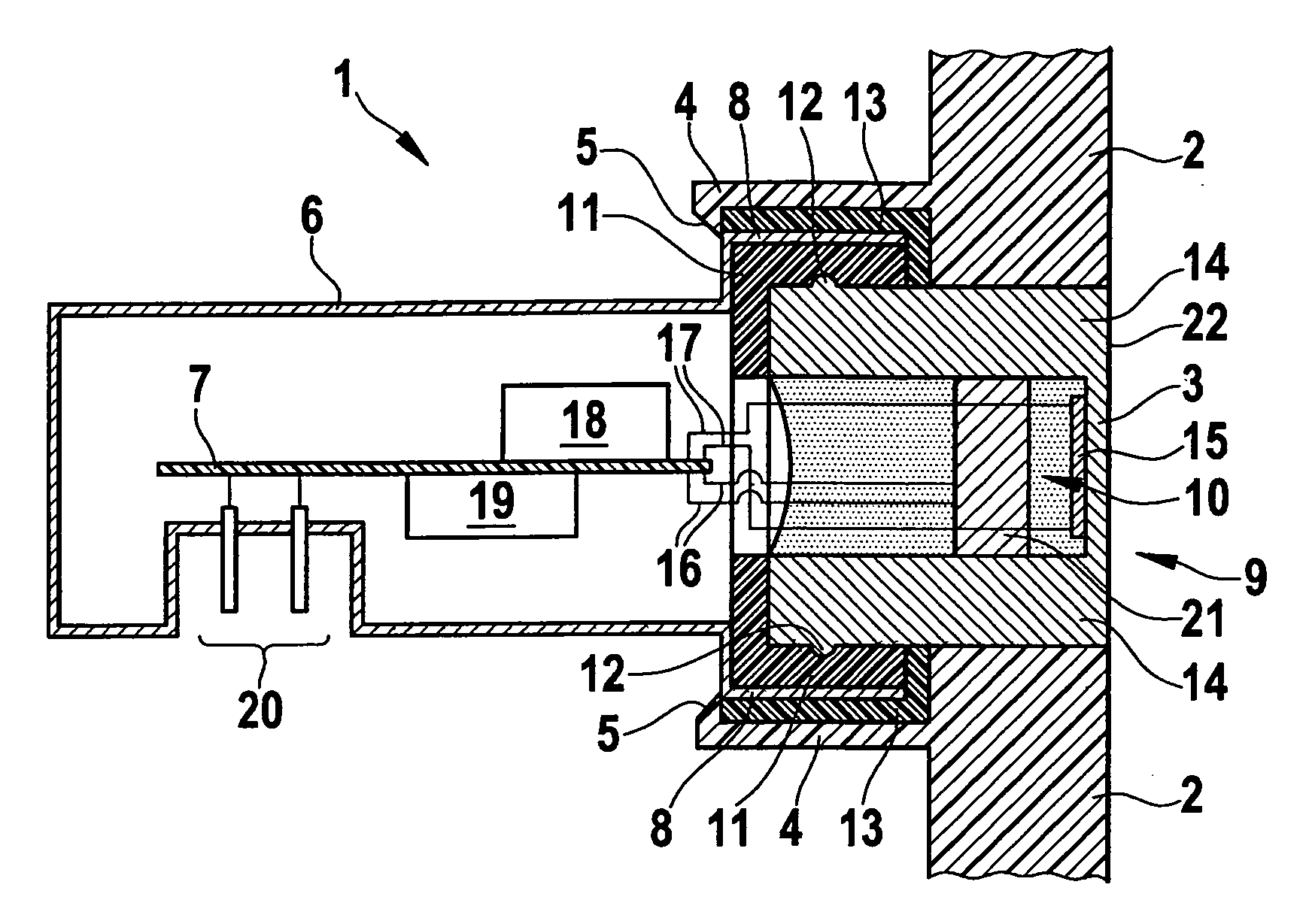
[0013]The ultrasonic sensor according to the present invention may be used for any ultrasonic measurements. Its use is practical, in particular, when the sensor is in danger of being covered by snow or ice during measurement. This is the case, in particular, when used outdoors, for example during wind measurement or distance measurement outdoors. Its use is advantageous, in particular, for ultrasonic distance sensors which are situated on vehicles and which measure the distance to obstacles in the vehicle's surroundings. The present invention is therefore explained below on the basis of an example of an ultrasonic distance sensor on a vehicle. The ultrasonic sensor in this case may act only as an ultrasonic receiver which receives ultrasonic waves originating from a different source. In a preferred specific embodiment, however, particularly when used in a vehicle, the ultrasonic sensor also acts as an ultrasonic transmitter which, in this case, emits ultrasonic waves in a first oper...


PUM

PropertyMeasurementUnit
temperatureaaaaaaaaaa
distanceaaaaaaaaaa

Abstract

An ultrasonic sensor having a diaphragm includes a heating element for heating the diaphragm.

Description

BACKGROUND INFORMATION[0001]Ultrasonic sensors are known in which a diaphragm is excited to vibration by ultrasonic waves. The sound waves are converted to an electrical signal by an electroacoustic transducer, for example a piezoelectric element, enabling the signal to be evaluated. In particular when used outdoors, the operation of the ultrasonic sensor may be impaired at low temperatures, for example by ice or snow, if the diaphragm of the ultrasonic sensor is covered thereby. The sound may be absorbed by snow. An ice covering may reduce the diaphragm's ability to vibrate. Furthermore, the ice covering on other components may also cause sound waves to become decoupled, so that the system sensitivity as a whole is reduced. An ultrasonic sensor which is inserted into a holder is described in U.S. Pat. No. 6,282,969. The holder includes a heating element which is used to heat the ultrasonic transducer and, in particular, also the diaphragm. Ice and snow, which may accumulate in fron...

Claims


Application Information

Patent Timeline
Patent Type & Authority Applications(United States)
IPC IPC(8): G01N29/11G01S15/931
CPCH04R17/00G01S15/931G01S2007/52011G01S7/521Y10S367/902G01S7/52004
Inventor RAPPS, PETERLUBIK, HANSHARTIG, OLIVER
Owner ROBERT BOSCH GMBH
Why Eureka
Try Eureka