Optical transceiver providing independent spaces for electrical components and for optical components

Inactive Publication Date: 2009-08-27
SUMITOMO ELECTRIC IND LTD
View PDF10 Cites 55 Cited by
  • Summary
  • Abstract
  • Description
  • Claims
  • Application Information

AI Technical Summary

Benefits of technology

[0010]The present invention, which is to provide a solution for subjects described above, has a feature to enhance the electrically shielding func

Problems solved by technology

As a characteristic wavelength becomes shorter, even a slight gap in the equipment, which conventionally causes no effect for the EMI leakage, results in a large EMI noise with high frequ

Method used


Image

  • Optical transceiver providing independent spaces for electrical components and for optical components
  • Optical transceiver providing independent spaces for electrical components and for optical components
  • Optical transceiver providing independent spaces for electrical components and for optical components

Examples


Example

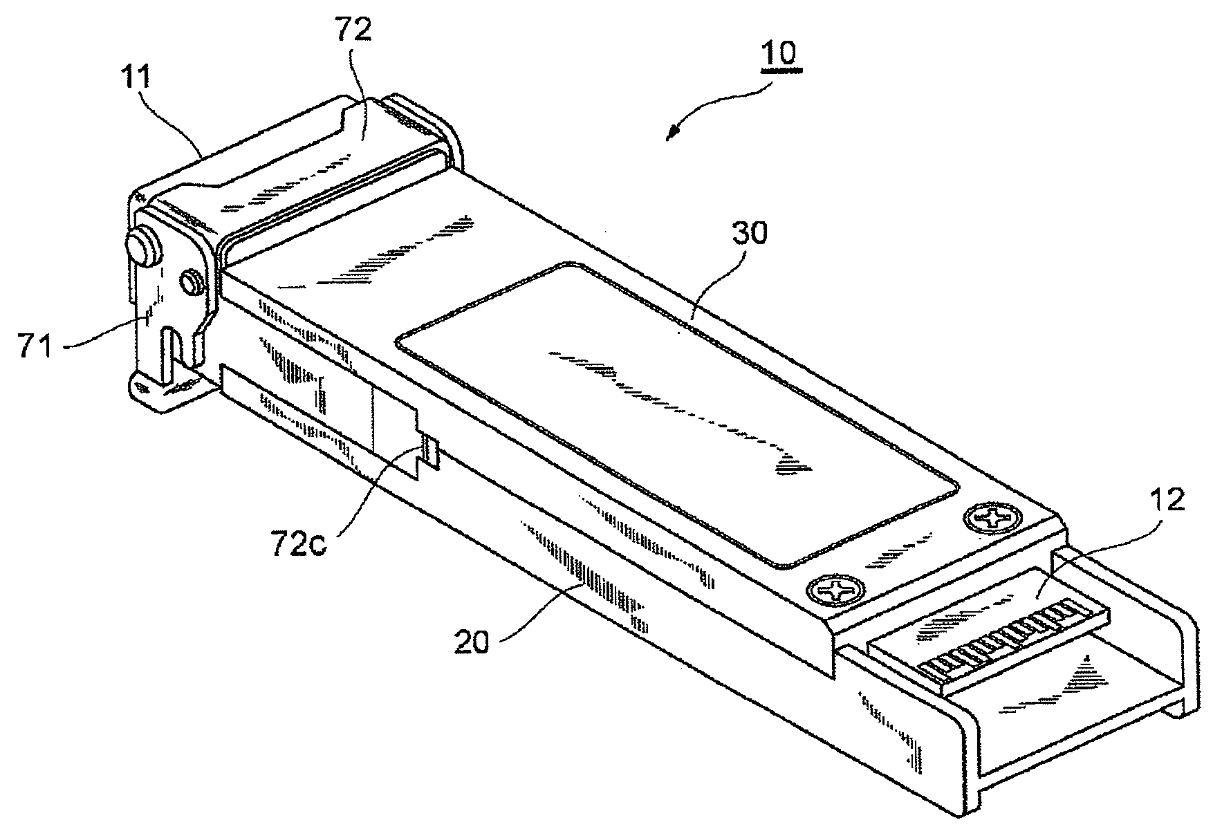
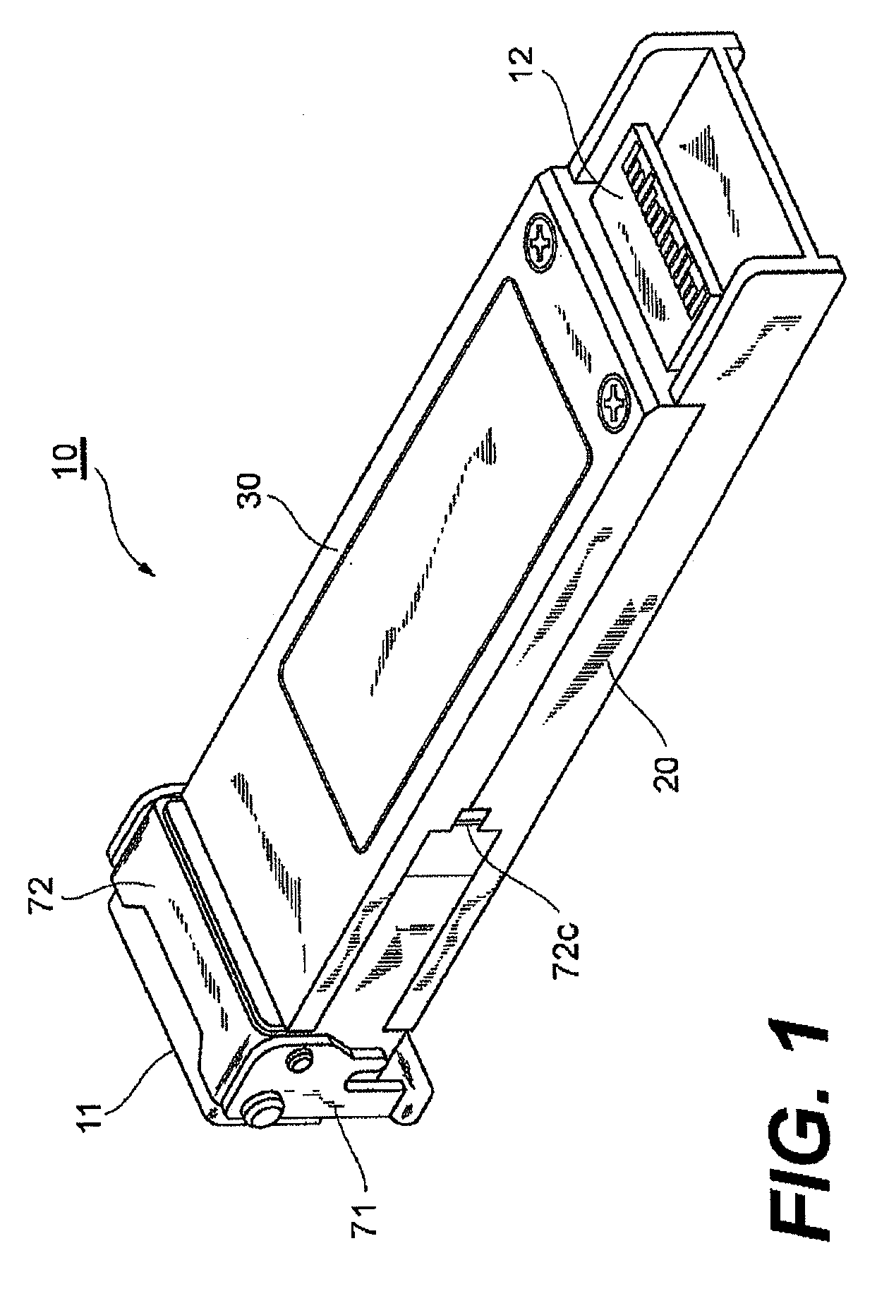
[0024]FIG. 1 is an external appearance of an optical transceiver 10, which is viewed from the bottom side thereof, according to an embodiment of the present invention. The optical transceiver 10 is a type of, what is called, an XFP transceiver whose outer dimensions and electrical specifications are defined by a multi-source agreement (MSA). The transceiver 10 has a housing with the dimension of 18.3×71.1×8.5 mm3 and may perform the optical communication with the full-duplex mode and of the transmission speed of 10 Gbps. The transceiver 10 provides an optical receptacle 11 to receive a duplex optical connector with the LC-type in the front side thereof, while, it provides, in the rear side, a plug connector 12 that is mated with an electrical connector prepared in the host system that installs the optical transceiver 10. Here, the front side corresponds to a side where the optical connector is mated, while, the rear side corresponds to a side where the electrical connector is mated....


PUM


Abstract

An optical transceiver that reduces the EMI noise leaked therefrom is reduced is disclosed. The optical transceiver of the invention provides a metal housing, an optical subassembly, and an electronic circuit. The metal housing includes a first space that installs the electronic circuit and a second space that installs the optical subassembly. The first space and the second space are electrically shielded to each other, in addition that both spaces are shielded from the external. In the optical transceiver of the invention, even the second space provides the optical path to the optical connector, which becomes a definite leak path for the EMI noise, the leakage from the first space to the external through the optical path is prevented.

Description

CROSS REFERENCE TO RELATED APPLICATIONS[0001]This application claims the benefit of U.S. Provisional Application No. 61 / 064,225, entitled “OPTICAL TRANSCEIVER WITH EMI SHIELDING AND FPC BOARD FIXED AND SECURED BY ELECTRICAL COMPONENT”, which is hereby incorporated by reference.BACKGROUND OF THE INVENTION[0002]1. Field of the Invention[0003]The present invention relates to an optical transceiver, in particular, the invention relates to an EMI shielding structure of the optical transceiver.[0004]2. Related Background Arts[0005]The U.S. Pat. No. 7,195,403, has disclosed an arrangement of the interconnection from the connector plug exposed in the external of the optical transceiver to the electronic circuit set within the transceiver. In this arrangement, the interconnection is buried within the substrate, while the top and the back surfaces of the substrate provide the ground patterns each coming in contact with the shield gasket, which is made of electrically conductive elastic materi...

Claims


Application Information

Patent Timeline
IPC IPC(8): H05K9/00
CPCG02B6/4246H05K9/0058G02B6/4292
Inventor EDWARDS, PHILLIP J.SHAH, JIGNESH H.THOMPSON, LANCE R.HUYNH, NHAN
Owner SUMITOMO ELECTRIC IND LTD
Why Eureka
Try Eureka