Plasma etching carbonaceous layers with sulfur-based etchants

a technology of sulfur-based etchants and carbonaceous layers, which is applied in the field of plasma etching features in carbonaceous layers, can solve the problems of small process windows, performance limitations that cannot be tuned out of the etching process with known means, and achieve the effect of improving the uniformity of the carbonaceous layer

Inactive Publication Date: 2009-08-27
APPLIED MATERIALS INC
View PDF4 Cites 41 Cited by
  • Summary
  • Abstract
  • Description
  • Claims
  • Application Information

AI Technical Summary

Benefits of technology

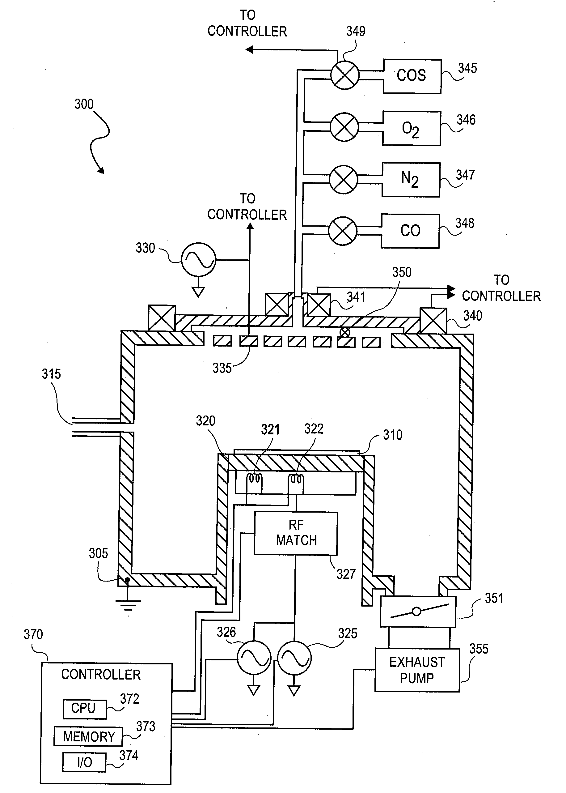
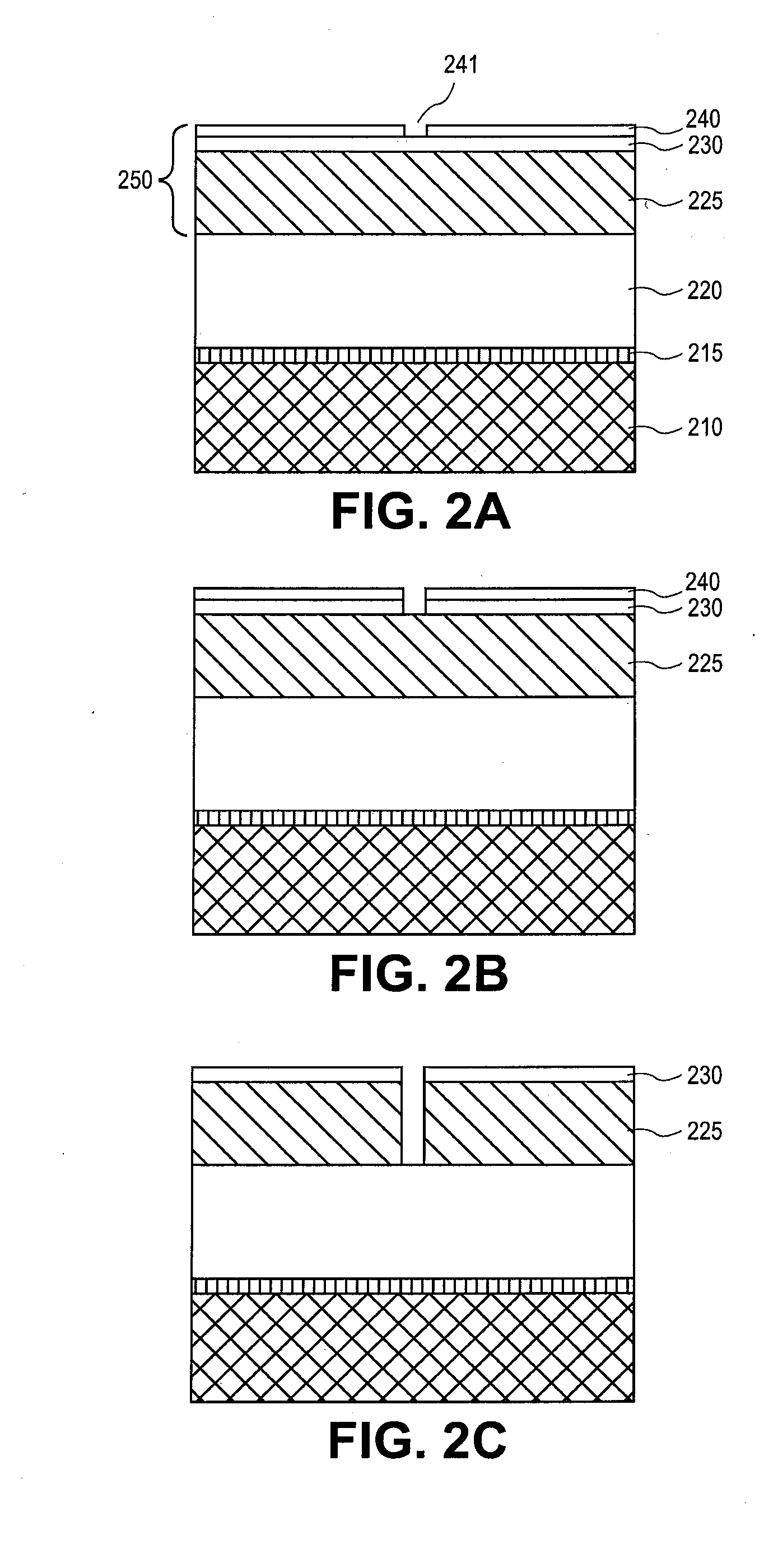
[0007]In an embodiment, the COS:O2 volumetric flow rate between about 0.25 and about 1.0 is energized with a capacitively coupled high frequency RF generator, having a frequency above about 100 MHz, to etch a carbonaceous layer with selectivity over a masking inorganic dielectric cap layer greater than at least 30:1 and preferably greater than 50:1 while incurring minimal bowing in sidewalls of HAR features, such as contact patterns. The COS:O2 etchant gas mixture may be advantageously further energized with one or more low frequency RF generators, having a frequency below about 60 MHz to further tune the feature CD uniformity.
[0008]In still other embodiments, an etchant gas mixture including a gas having a carbon sulfur terminal ligand is delivered to the plasma etch chamber with a gas flow rate at a first gas inlet proximate to a substrate center different than the gas flow rate at a second orifice proximate to the substrate periphery while the plasma is exposed to a magnetic field strength proximate to the substrate center different than the magnetic field strength proximate to the substrate periphery to further improve uniformity of the carbonaceous layer etch.

Problems solved by technology

When such demanding aspect ratios and CD control are compounded with requirements of high etch selectivity, sidewall smoothness and high tool throughput, the process window for any hardware configuration can become very small.
However, such small process windows typically suffer from performance limitations which cannot be tuned out of the etch process with known means.

Method used


Image

  • Plasma etching carbonaceous layers with sulfur-based etchants
  • Plasma etching carbonaceous layers with sulfur-based etchants
  • Plasma etching carbonaceous layers with sulfur-based etchants

Examples


Embodiment Construction

[0016]In the following description, numerous specific details are set forth to provide a thorough understanding of the present invention. It will be apparent to one skilled in the art that the present invention may be practiced without these specific details. In other instances, well-known features, such as specific lithographic patterning and etching techniques, are not described in detail in order to not unnecessarily obscure the present invention. Reference throughout this specification to “an embodiment” means that a particular feature, structure, material, or characteristic described in connection with the embodiment is included in at least one embodiment of the invention. Thus, the appearances of the phrase “in an embodiment” in various places throughout this specification are not necessarily referring to the same embodiment of the invention. Furthermore, the particular features, structures, materials, or characteristics may be combined in any suitable manner in one or more em...


PUM

PropertyMeasurementUnit
RF frequencyaaaaaaaaaa
frequencyaaaaaaaaaa
frequencyaaaaaaaaaa

Abstract

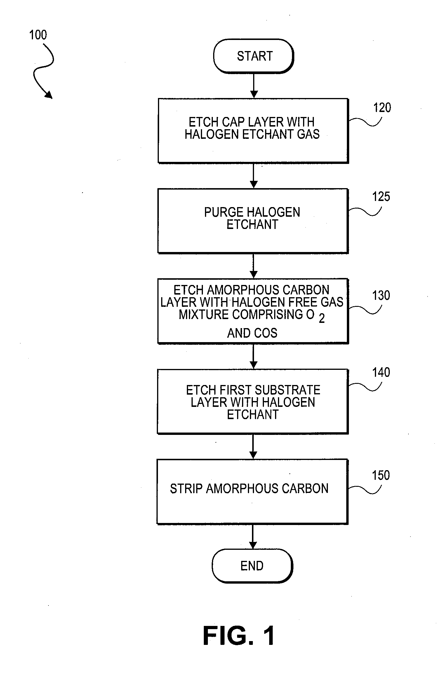
Etching of carbonaceous layers with an etchant gas mixture including molecular oxygen (O2) and a gas including a carbon sulfur terminal ligand. A high RF frequency source is employed in certain embodiments to achieve a high etch rate with high selectivity to inorganic dielectric layers. In certain embodiments, the etchant gas mixture includes only the two components, COS and O2, but in other embodiments additional gases, such as at least one of molecular nitrogen (N2), carbon monoxide (CO) or carbon dioxide (CO2) may be further employed to etch to carbonaceous layers.

Description

BACKGROUND[0001]1. Field[0002]Embodiments of the present invention relate to the electronics manufacturing industry and more particularly to the process of plasma etching features in carbonaceous layers.[0003]2. Discussion of Related Art[0004]As the feature size of the device patterns get smaller than 100 nm, the critical dimension (CD) requirement of features becomes a more important criterion for stable and repeatable device performance. Allowable CD variation across a substrate has also scaled with the scaling of feature CD. For example, across a 300 mm diameter substrate, some applications may demand a 3-sigma of less than 10 nm for a target CD averaging about 80 nm.[0005]Also, with lateral dimensions scaling faster than vertical dimensions, because of issues such as device capacitance, high aspect ratios (HAR) are now prevalent in the industry. When such demanding aspect ratios and CD control are compounded with requirements of high etch selectivity, sidewall smoothness and hig...

Claims


Application Information

Patent Timeline
Patent Type & Authority Applications(United States)
IPC IPC(8): C23F1/00
CPCH01L21/31138H01L21/31116H01L21/3065
Inventor WANG, JUDYMA, SHAWMINGHSIEH, CHANG-LINLIAO, BRYANZHOU, JIEKIM, HUN SANG
Owner APPLIED MATERIALS INC
Why Eureka
Try Eureka