Method for operating a wind energy plant and wind energy plant

a technology of wind energy plant and wind energy, which is applied in the direction of motors, engine control, engine fuctions, etc., can solve the problems of reducing the power of the wind energy plant generator, the torque or the generator power of the wind energy plant falls to zero, and the excess rotation speed of the rotor or the generator is detrimental, so as to achieve the effect of simple manner, fast regulation action and very rapid generation

Active Publication Date: 2009-08-27
NORDEX ENERGY SE & CO KG
View PDF11 Cites 14 Cited by
  • Summary
  • Abstract
  • Description
  • Claims
  • Application Information

AI Technical Summary

Benefits of technology

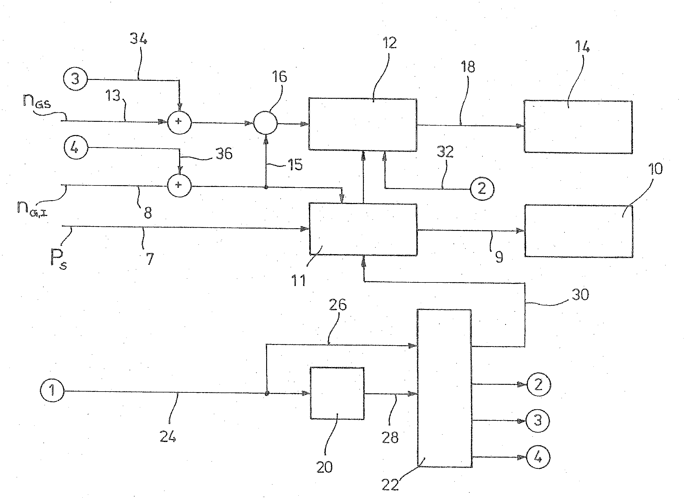
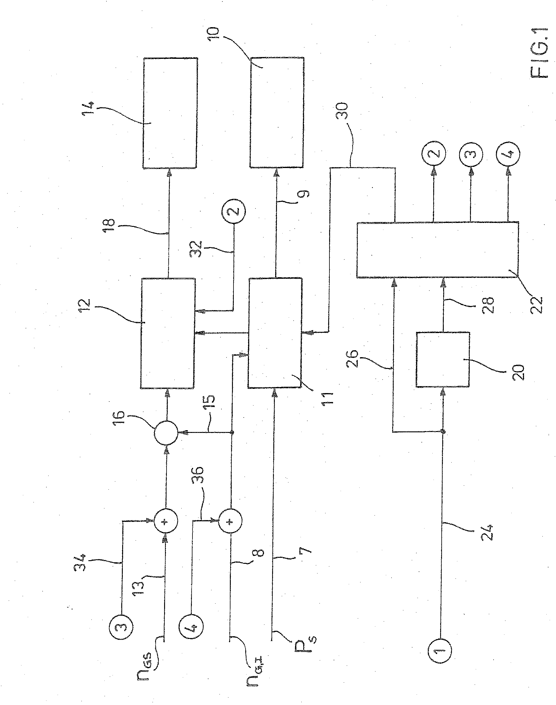
[0019]With regard to practice, it is especially feasible if the preset value is the preset generator torque or the preset generator power. According to a further especially feasible aspect, the electrical quantity can be the active power actually provided by the wind energy plant. According to another aspect, the adjustment of the new pitch angle can be performed by reducing by a defined offset a rotation speed set point supplied to the regulation means. The pitch controller establishes the difference between a rotation speed set point supplied to the pitch controller and a current rotation speed supplied to the pitch controller for example by a measurement device. In so far as a deviation is detected, the pitch angle is changed by the controller. By subtracting an offset signal from the rotation speed set point supplied to the controller, within the controller a large set point / current value difference can be generated very quickly, leading to a correspondingly fast regulation action by the controller. For the adjustment of the new pitch angle, a switching on of a disturbance variable is performed in an especially simple manner. According to an alternative or additional approach to the adjustment of the new pitch angle, a rotation speed set point supplied to the regulation means can be increased by a defined offset. Furthermore, a minimal and a maximal pitch angle are usually given to the regulation means, limiting the adjusting range of the controller. In this way, the controller can determine pitch angles only within the limits formed by the minimal and maximal angles. The maximum pitch angle usually is about 90° for all operating states, that is flag position of the rotor blade. The minimal pitch angle depends on the operating state of the plant. In regular production mode, it is usually 0°. An alternative or additional option for adjusting the new pitch angle therefore is to increase the minimal pitch angle supplied to the regulation means by a defined offset. With this design as well, a regulation action can be initiated quickly and in an especially simple manner.
[0020]By adding a defined offset, that is a defined value, to an input variable of the regulation means, a fast influence on the regulation means is possible. Therein, the offset is defined such that the pitch angle desired in each case is adjusted quickly. For example, the offset values can be determined empirically and retained in characteristic diagrams. It is possible to add a defined offset to only one or to a plurality of input variables of the regulation means. The offset can be cancelled after a certain time and / or when going below a predetermined rotation speed of the generator or rotor. According to another aspect, the offset can be reduced over time to zero starting from an initial maximum value. In this aspect, the regulation means is therefore put down to its regular operating mode over time with the regular input variables for compensation of wind turbulences, by means of reducing the added offset over time to zero.
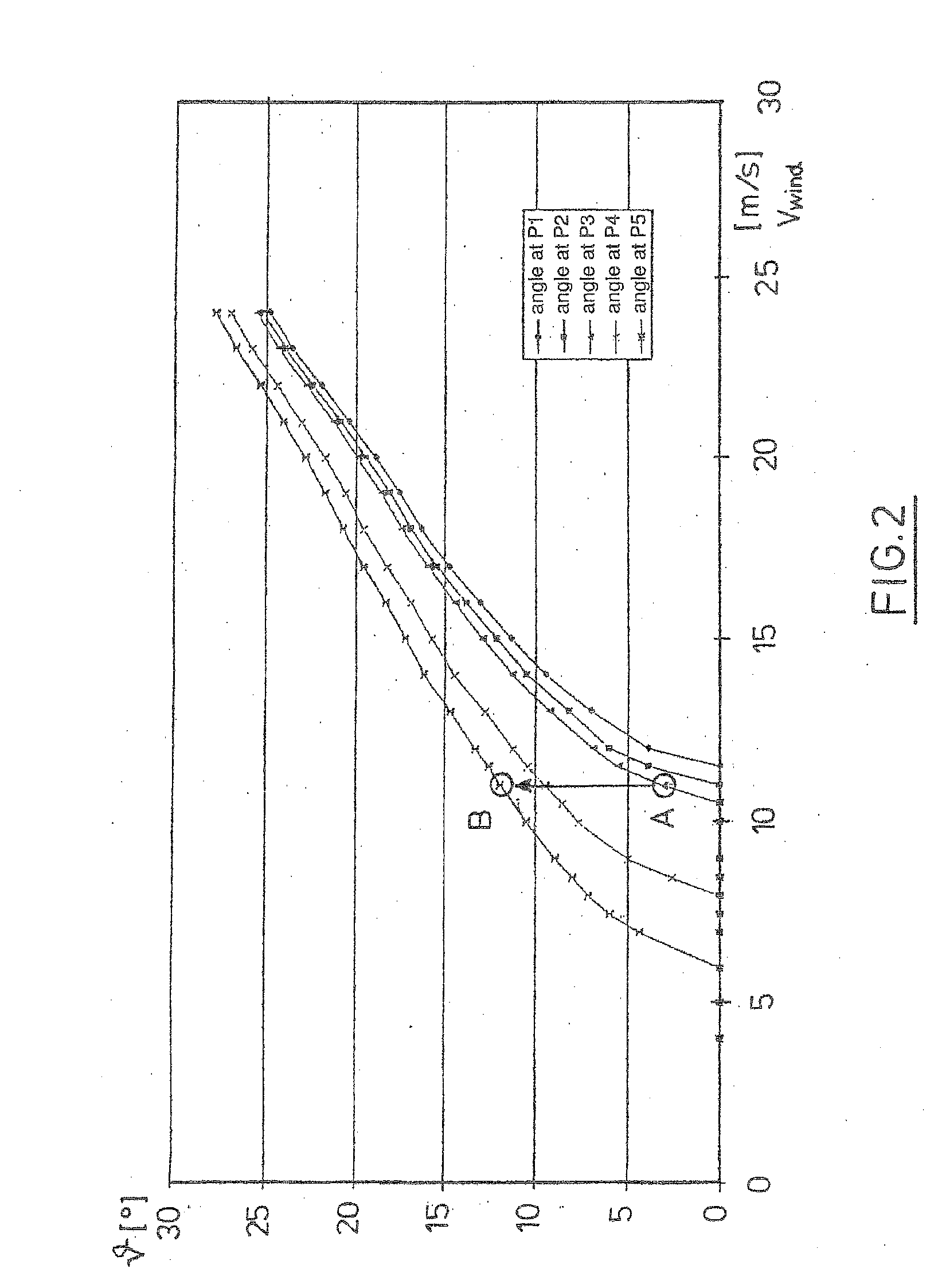
Problems solved by technology

Fault of a grid which is fed by the wind energy plant may cause a sudden load shedding, wherein the generator torque or the generator power of the wind energy plant falls off to zero within a very short time period.
Through this reduction of the counter load generated by the generator, however, the rotor of the wind energy plant is accelerated and rotation speeds occur which cause the regulation means to interact by increasing the pitch angle.
This can lead to detrimental excess rotation speeds of the rotor or the generator, respectively.
For this reason, it is difficult to fulfil the strict requirements of the energy supply companies with current systems.
In particular for wind parks, an additional problem is that the request for a reduction of the overall active power provided must be allocated to the individual wind energy plants in an intelligent manner.
Receiving, evaluating and transmitting the individual set point signals to the plants by means of the wind park controller takes a certain time, which is then no longer available for a reduction of the load by the plants.
The aforementioned problem is therefore getting worse for plants in wind parks.
With known systems, it is not possible to change the active power of a wind energy plant to 20% of the rated power within a few seconds, for example within five seconds.
In the alternative, the electrical quantity provided can be reduced by disconnecting the plant from the grid, that is, by a shutdown, but this is often undesirable.

Method used


Image

  • Method for operating a wind energy plant and wind energy plant
  • Method for operating a wind energy plant and wind energy plant
  • Method for operating a wind energy plant and wind energy plant

Examples


Embodiment Construction

[0028]While this invention may be embodied in many different forms, there are described in detail herein a specific preferred embodiment of the invention. This description is an exemplification of the principles of the invention and is not intended to limit the invention to the particular embodiment illustrated

[0029]In FIG. 1, a block diagram is shown illustrating the operation of the wind energy plant of the invention. The wind energy plant has, in a manner known as such, a power train not shown in detail which carries at its front end a rotor also not shown having at least one, preferably three rotor blades not shown, and which leads to a so-called generator converter unit at is rear end. The generator converter unit has a generator not shown, a converter 10 and a converter controller 11 controlling the converter 10 through a control channel 9. By means of the converter controller 11, the active power actually provided by the plant is adjustable. The generator converter unit is no...


PUM


Abstract

The invention relates to a method for operating a wind energy plant, the wind energy plant having a rotor with at least one rotor blade which has an adjustable pitch angle, the wind energy plant having a generator coupled to the rotor, and a regulation means which, if a there is a deviation of the rotation speed of the generator or rotor from a rotation speed set point, adjusts the pitch angle of the at least one rotor blade such that the rotation speed set point is reached again, wherein an electrical quantity provided by the wind energy plant by means of a generator and fed into a grid is reduced to a predetermined value in a short time by a reduction of a preset value for the generator, wherein prior to the regulation means noticing a deviation of the rotation speed of the rotor or generator from the rotation speed set point effected by the reduction of the preset value, an adjustment of the at least one rotor blade to a new pitch angle is initiated, wherein at the new pitch angle the rotation speed of the rotor or the generator reaches the rotation speed set point at the reduced electrical quantity and the current wind speed. In addition, the invention relates to a wind energy plant.

Description

CROSS-REFERENCE TO RELATED APPLICATIONS[0001]Not applicable.STATEMENT REGARDING FEDERALLY SPONSORED RESEARCH[0002]Not applicable.BACKGROUND OF THE INVENTION[0003]The invention relates to a method for operating a wind energy plant and to a wind energy plant having a rotor with at least one rotor blade which has an adjustable pitch angle, a generator coupled to the rotor, and a regulation means which, if there is a deviation of the rotation speed of the generator or rotor from a rotation speed set point, adjusts the pitch angle of the at least one rotor blade such that the rotation speed set point is reached again.[0004]Fault of a grid which is fed by the wind energy plant may cause a sudden load shedding, wherein the generator torque or the generator power of the wind energy plant falls off to zero within a very short time period. Moreover, it is also possible to reduce an electrical quantity provided by the plant by means of a generator and fed into a grid to a predetermined value i...

Claims


Application Information

Patent Timeline
Patent Type & Authority Applications(United States)
IPC IPC(8): F03D7/04F03D9/00H02P9/04
CPCF03D7/0224F03D7/0276F03D7/028F03D7/043Y02E10/723F05B2270/1011F05B2270/1014F05B2270/1071F05B2270/327F05B2260/70Y02E10/72
Inventor HARMS, ULRICHKABATZKE, WOLFGANGJURKAT, MARK
Owner NORDEX ENERGY SE & CO KG
Why Eureka
Try Eureka