
Positioning device for a free-flying kite-type wind-attacked element in a wind-powered watercraft

a kite-like element and positioning device technology, which is applied in the direction of electric generator control, special-purpose vessels, vessel construction, etc., can solve the problem of not being able to adjust the known apparatus

Active Publication Date: 2009-08-27
SKYSAILS GMBH & CO KG
View PDF12 Cites 10 Cited by
  • Summary
  • Abstract
  • Description
  • Claims
  • Application Information

AI Technical Summary

Benefits of technology

"The patent describes a positioning apparatus for a wind-actuated element that can be automatically adjusted to different wind conditions. The apparatus includes a hawser and a winch on a watercraft. The length of the hawser is adjusted automatically based on the wind conditions, so that the element stays in the air. The winch can initiate a pulling-in or paying-out process only when the wind speed exceeds a certain threshold. The apparatus also includes a sensor to detect flow separation and a converter to control the winch speed. The length of the hawser is gradually increased again once the wind speed exceeds a predetermined threshold value to ensure stable operation of the element. The winch has a predetermined torque / cable-length characteristic to absorb cable shocks. The wind speed during stowage should ensure the minimum incident-flow speed to maintain the element's flying capability. The apparatus can be used in high sea states and can adapt to different wind directions. The winch is driven by a pressure medium, which allows for safe operation and complies with safety requirements."

Problems solved by technology

However, this does not relate to a winch which is suitable for adjustment of an element on which wind acts, in accordance with the wind conditions, for a watercraft with wind propulsion, but relates only to keeping a general aeronautical object at a constant height.
It is not possible to adjust the known apparatus on the basis of the wind conditions.

Method used


Image

  • Positioning device for a free-flying kite-type wind-attacked element in a wind-powered watercraft
  • Positioning device for a free-flying kite-type wind-attacked element in a wind-powered watercraft
  • Positioning device for a free-flying kite-type wind-attacked element in a wind-powered watercraft

Examples


Embodiment Construction

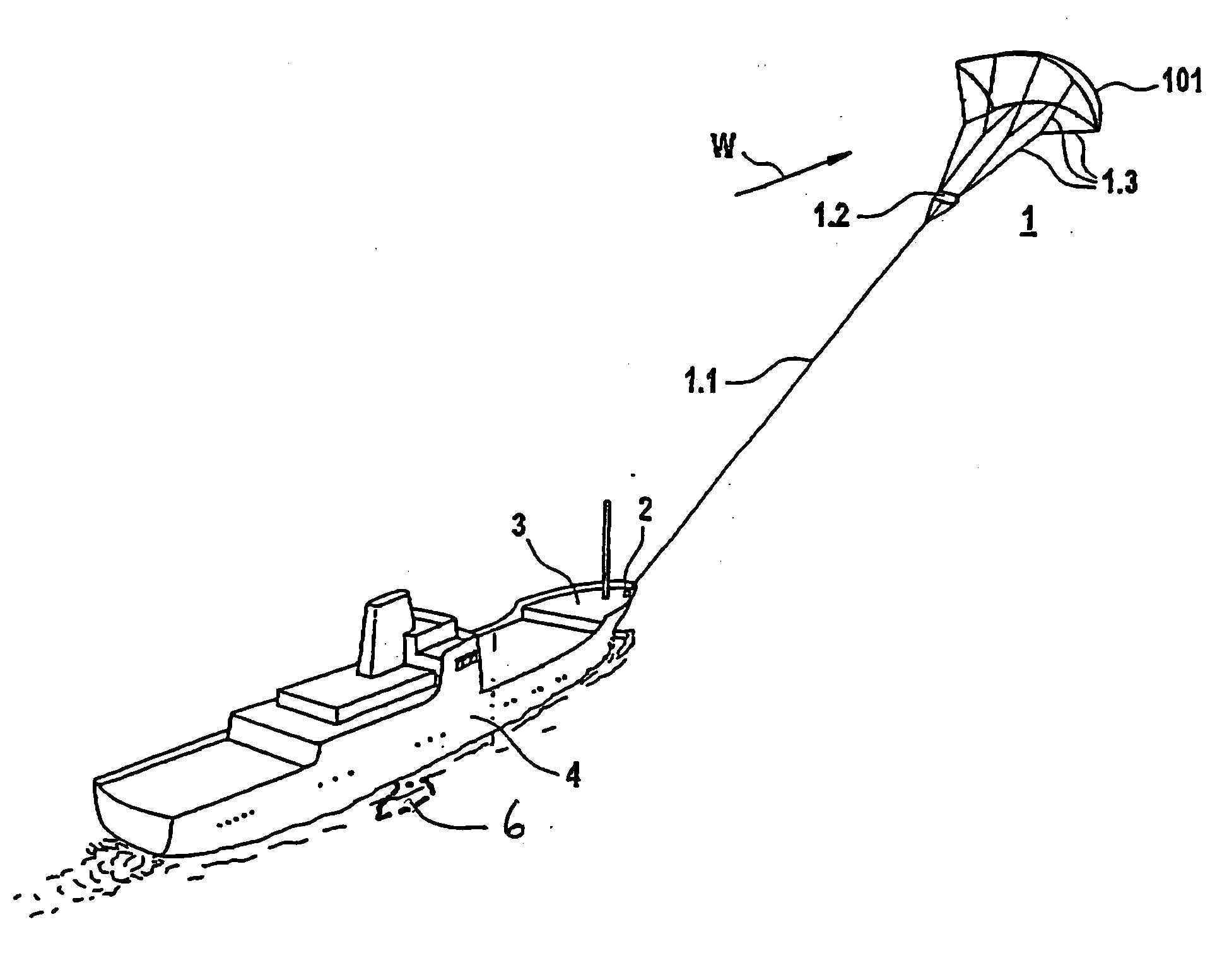
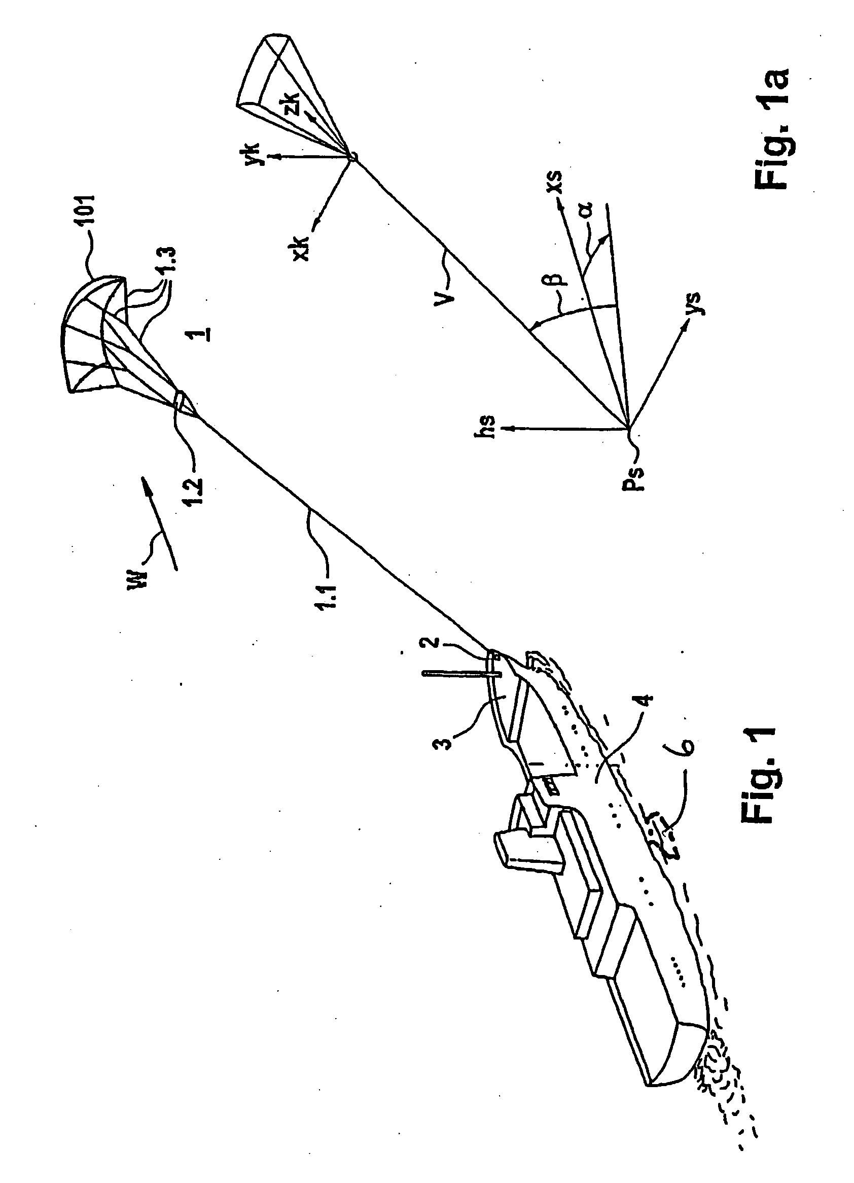
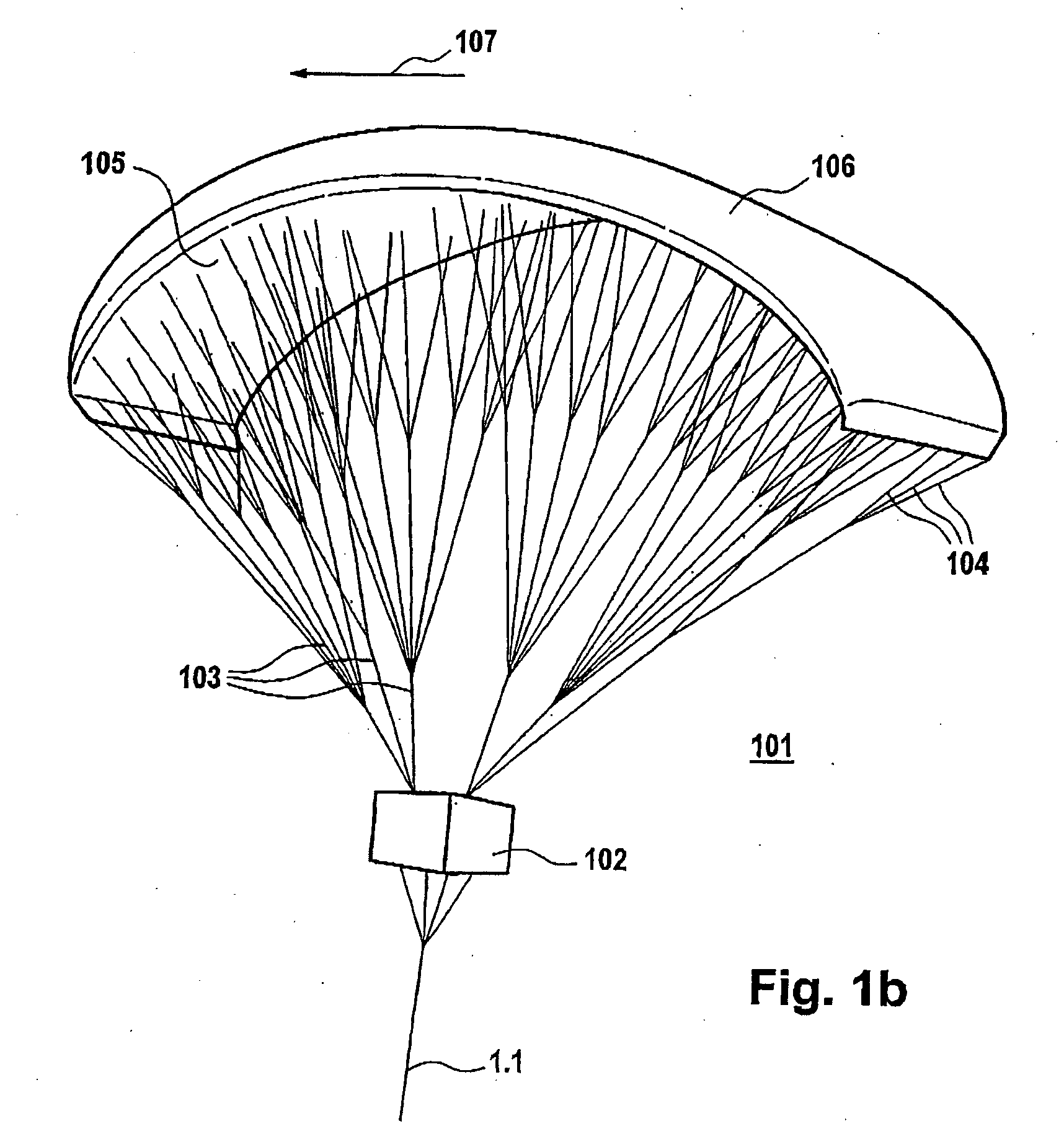
[0047]FIG. 1 shows an oblique plan view of a vessel which is being towed by the kite system. In this case, an element 1 on which wind acts is connected to a vessel 4 via a hawser 1.1 with an apparatus 2 on which force acts and which is provided in the bow area of the vessel 4. The hawser 1.1 is passed to a central gondola 1.2, from which a number of holding lines 1.3 originate, which are passed to the element 1 on which wind acts and is in the form of a paraglider with a kite profile, giving it the necessary shape. The details relating to this will be explained further below in the description. The apparent wind direction in the area of the element 1 on which wind acts is annotated W. The corresponding wind vector is indicated by its magnitude and direction. If required, its rate of change is also indicated by a variable B, which denotes the gusting, forms the mean time discrepancy between the wind speed and its mean value and can be represented as a scalar, which effectively forms ...


PUM


Abstract

Disclosed is a positioning device for a free-flying kite-type wind-attacked element that comprises a profiled wing, is used as the exclusive, an auxiliary, or an emergency drive unit, and is connected to a watercraft via a traction rope. The positioning device is provided with a winch that encompasses means which cause the traction rope to be taken in when a given first tractive force is not attained and / or when the flow is about to stop or has stopped abruptly and / or cause the traction rope to be veered when given a second tractive force and / or a given inflow velocity are / is exceeded.

Description

CROSS-REFERENCE TO RELATED APPLICATION[0001]This application is a continuation of U.S. patent application Ser. No. 11 / 578,817 filed Oct. 19, 2006, which is the U.S. National Phase of International Application No. PCT / EP2005 / 004183 filed Apr. 19, 2005.BACKGROUND OF THE INVENTION[0002]The invention relates to a positioning apparatus for a freely flying kite-like element on which wind acts for a watercraft with wind propulsion.[0003]A positioning apparatus such as this is known from U.S. Pat. No. 2,433,344. However, this does not relate to a winch which is suitable for adjustment of an element on which wind acts, in accordance with the wind conditions, for a watercraft with wind propulsion, but relates only to keeping a general aeronautical object at a constant height. It is not possible to adjust the known apparatus on the basis of the wind conditions.SUMMARY OF THE DISCLOSURE[0004]A positioning apparatus of the generic type indicated initially which does not have the stated disadvant...

Claims


Application Information

Patent Timeline
Patent Type & Authority Applications(United States)
IPC IPC(8): F03B13/00B63H9/06
CPCB63H2009/0692B63H9/0685B63H9/072B63H9/071Y02T70/5236B63B2035/009
Inventor WRAGE, STEPHAN
Owner SKYSAILS GMBH & CO KG
Learn More