Electrohydraulic Braking System Comprising Vehicle Dynamics Control
- Summary
- Abstract
- Description
- Claims
- Application Information
AI Technical Summary
Benefits of technology
Problems solved by technology
Method used
Image

Examples
first embodiment
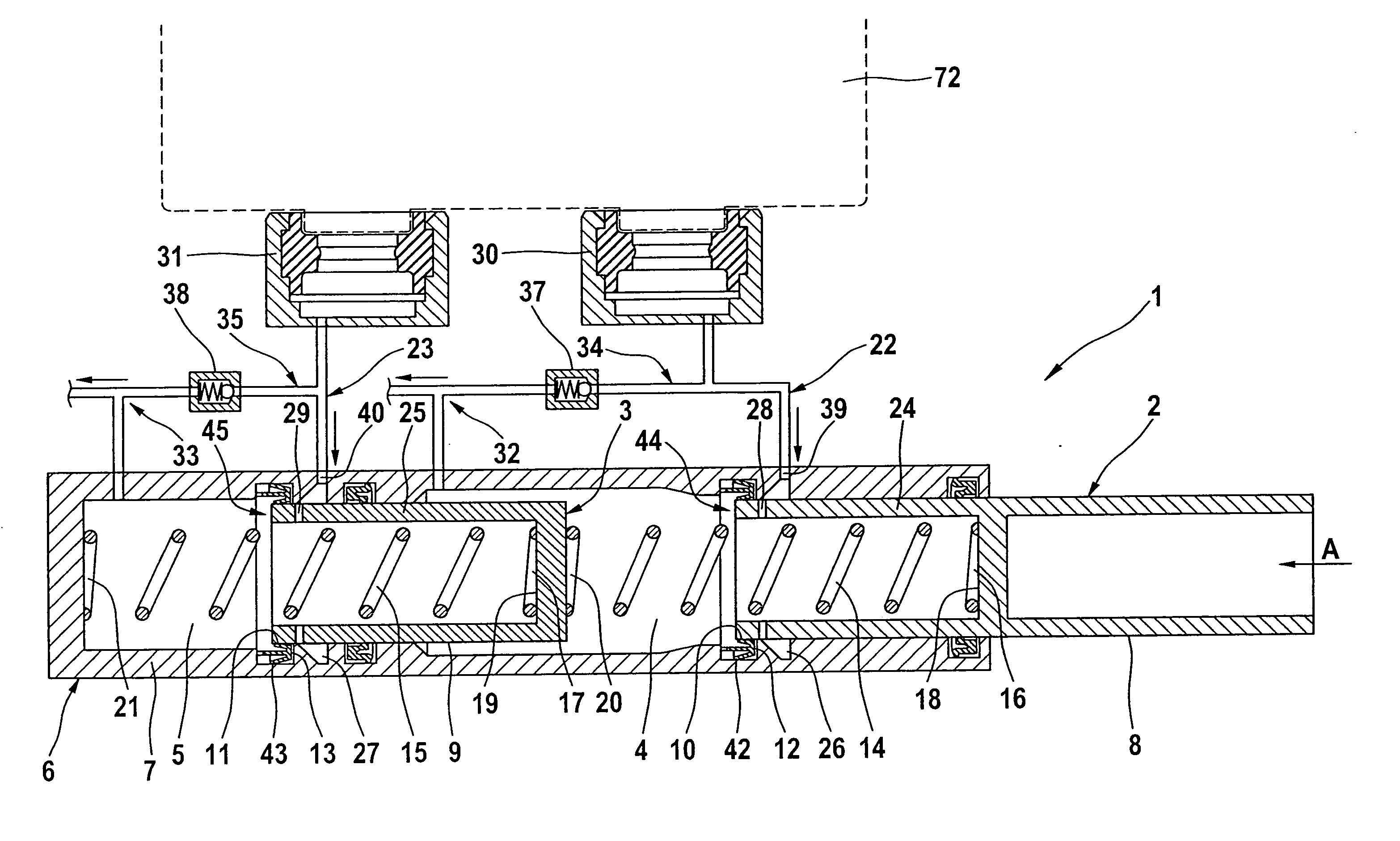
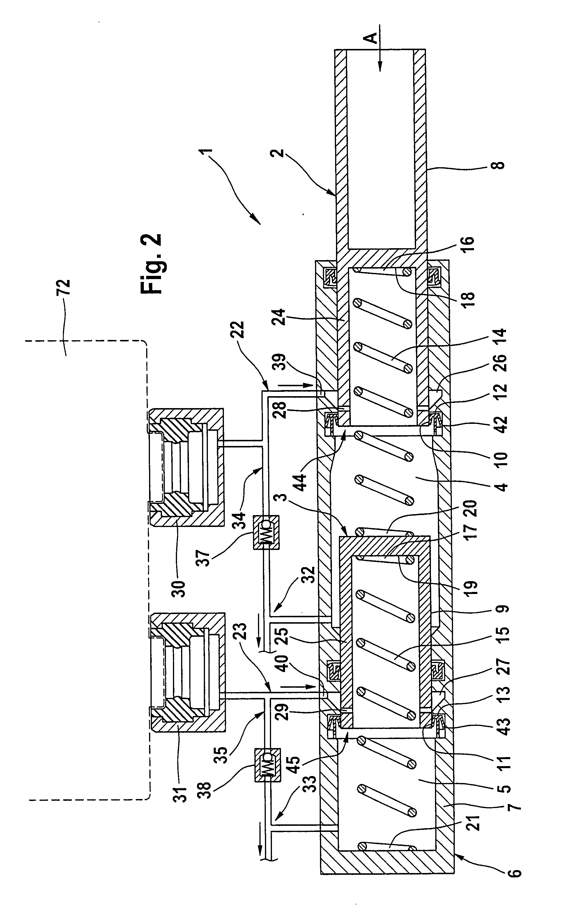
[0031]FIG. 2 shows a master cylinder 1 of an electrohydraulic brake system of the invention including driving dynamics control such as ESP. The mode of operation of a master cylinder 1 of this type is principally known in the art so that only the features that are essential to the invention will be described.
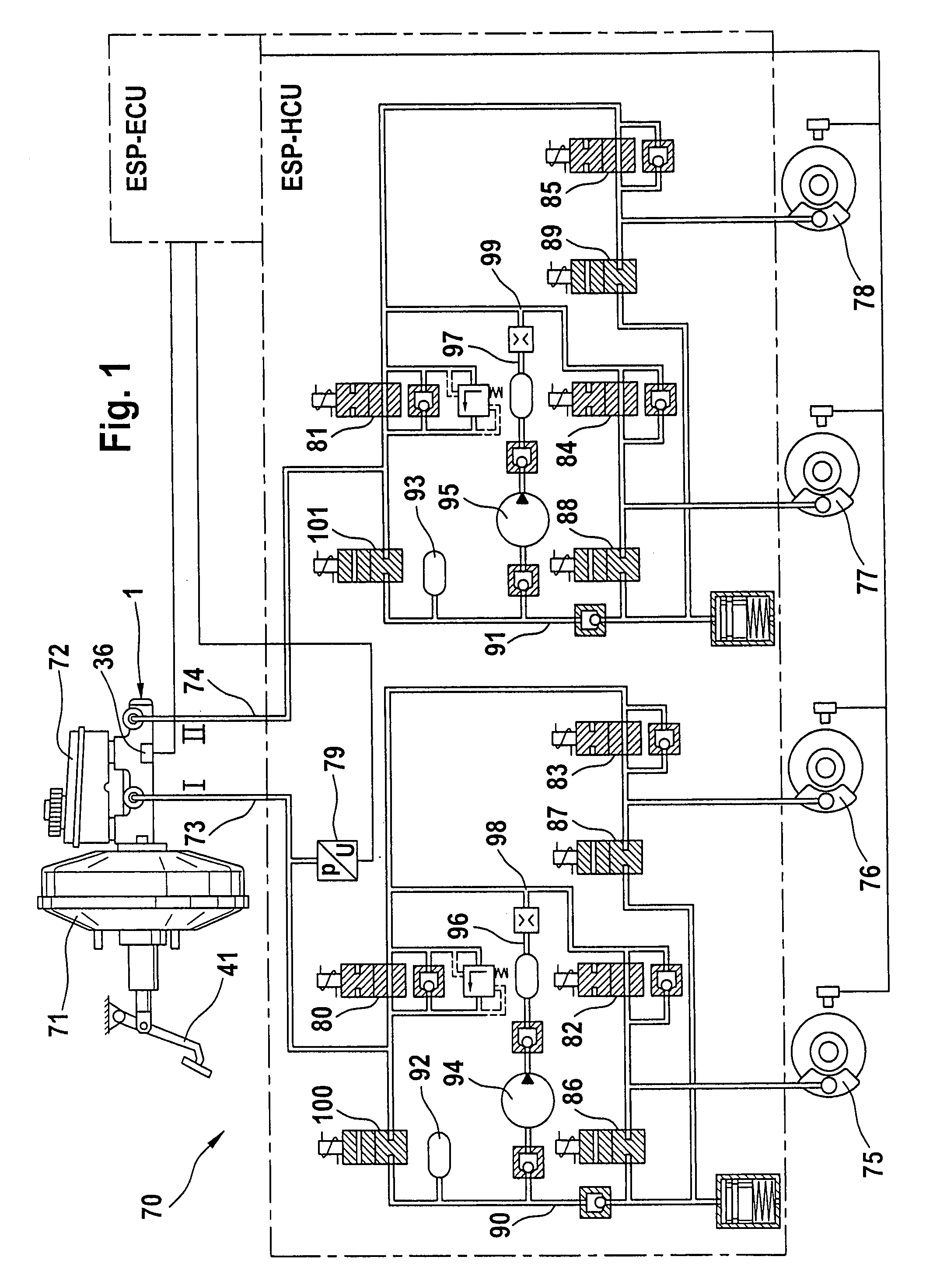
[0032]The master cylinder 1 with a first and a second piston 2, 3 for a first and a second pressure chamber 4, 5 is operable by means of a brake pedal 41 illustrated in FIG. 1, which is connected indirectly or directly to the first piston 2, with the pistons 2, 3 being displaceably arranged inside a housing 6 of the master cylinder 1 for the pressure fluid supply of the wheel brakes 75 to 78.
[0033]The master cylinder 1 is of the so-called plunger type with stationary sealing cups 12, 13 arranged in a wall 7 of housing 6 and abutting on a piston wall 8, 9 with an inside sealing lip 10, 11 for sealing the pressure chambers 4, 5. Fluid can flow over outside sealing lips 42, 43 of t...
second embodiment
[0036]To improve the assembly, it is also feasible within the limits of the invention, as indicated in the second embodiment according to FIG. 4, to provide the pistons 2, 3 together with the resetting springs 14, 15 as a pre-assembled unit. For example, a cylindrical peg 46, 47 illustrated in FIG. 4 can be provided for this purpose, which, starting from the piston bottom 18, 19, extends centrically through the bowl-shaped wall 24, 25 of the pistons 2, 3 and ends before its axial exit from the wall 24, 25. This end can be provided with a stop 48 for a sleeve 49 that cooperates with a collar 50 in such a fashion that the sleeve 49 can be telescoped within limits in relation to the peg 46, 47. Upon actuation, the sleeve 49 with resetting spring 14, 15 can be urged into the interior of the piston. The stop 48 for the sleeve 49 can be an annular washer, which is riveted, in particular wobble-riveted, to the peg 46, 47. The other end of sleeve 49 can have a plate-type collar 51 for abutm...
third embodiment
[0054]FIG. 5 shows a cross-sectional view of a master cylinder 1 in the area of the pressure chamber 5 of the second brake circuit II of a As is obvious, the master cylinder 1 has an additional dome 62, into which the valve 38 designed as a spring-loaded non-return valve is introduced. Valve 38 has a similar design as valve 37 according to FIG. 4 and comprises a valve seat 63, a valve pin 64, a valve accommodation 65, and a valve spring 66. A closing cap 67 is fastened and sealed in the dome 62 by means of an annular sealing element 68 and a securing element 69 and safeguards the position of the valve 38. A disc 110 serves as a filter, on the one hand, and can also be provided as a restrictor for the pressure fluid flow limitation, on the other hand.
[0055]The bypass channel 59 and a pressure fluid channel 61 of this embodiment are shown in detail with respect to FIG. 6.
PUM
 Abstract
Description
Claims
Application Information
PatSnap Eureka turns technology decisions into work you can execute. Powered by our Innovation Knowledge Graph, it runs expert workflows across engineering, life sciences, materials and intellectual property. Get your review-ready output in minutes.


