Liquid crystal display

a technology of liquid crystal display and liquid crystal, which is applied in the field of liquid crystal display, can solve the problems of deteriorating leakage, reducing aperture ratio, and touch mura phenomenon on the lcd, and achieves the reduction of the degree of bending of the panel, reducing the shift distance of the black matrix on the color filter substrate, and reducing the spacing

Active Publication Date: 2009-08-27
BEIJING BOE OPTOELECTRONCIS TECH CO LTD
View PDF7 Cites 7 Cited by
  • Summary
  • Abstract
  • Description
  • Claims
  • Application Information

AI Technical Summary

Benefits of technology

[0013]In the operation of the LCD according to the embodiments of the present invention, the protection layer disposed between the panel and the optical sheet can reduce the spacing allowing for the bending of the panel. Therefore, when the panel is bended under an external force, due to the support of the protection layer, the degree of bending of the panel can be reduced, and in turn the shift distance of the black matrix on the color filter substrate can be reduced, thus the light leakage, and the touch mura phenomenon can be alleviated and the display quality of the LCD can be improved.
[0014]In the embodiments of the present embodiment, protrusions are disposed on both sides of the protection layer, thus keeping a desired spacing between the protection layer and the adjacent parts, in particular, the optical sheet, so that the optical sheet can be protected and the friction between the panel and the optical sheet can be prevented in order to reduce the contact wearing and improve the durability of the product. Furthermore, in the present embodiment, the area of the black matrix is not increased and the aperture ratio of the LCD is not decreased, and thus the transmittance and the display brightness is not affected.

Problems solved by technology

The further the panel is bended, the larger the black matrix would be shifted, thus deteriorating the leakage, which causes a touch mura phenomenon on the LCD.
Increasing the area of the black matrix on the color filter substrate can prevent the light leakage even if the black matrix was shifted by a distance due to the bending of the liquid crystal panel, however, in that case, the aperture ratio is decreased and the brightness of the LCD is compromised.

Method used


Image

  • Liquid crystal display
  • Liquid crystal display
  • Liquid crystal display

Examples


first embodiment

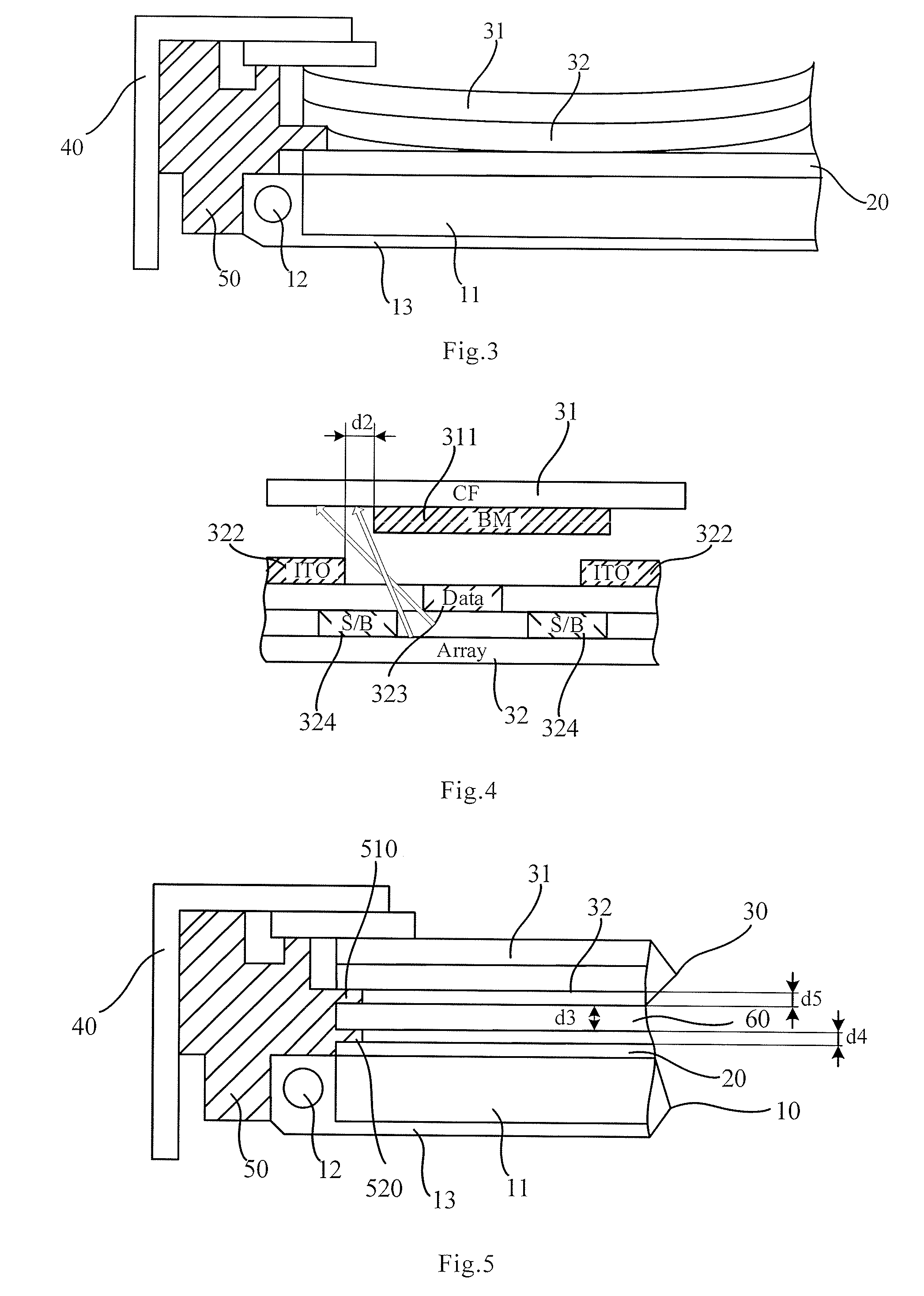
[0025]FIG. 5 is a schematic view showing the LCD according to the first embodiment of the present invention. As shown in FIG. 5, the LCD can comprise a backlight unit 10, an optical sheet 20 disposed above the backlight unit 10, and a liquid crystal panel 30 disposed above the optical sheet 20. A protection layer 60 is disposed between the liquid crystal panel 30 and the optical sheet 20 in order to support the liquid crystal panel 30 when the liquid crystal panel 30 is bended. The LCD can further comprise an outer frame 40 disposed on at least one side of the LCD and a mold frame 50 disposed between the outer frame 40 and the stacked assembly including the backlight unit 10, the optical sheet 20 and the panel 30. Thus the mold frame 50 is also disposed on the side of LCD.

[0026]In the LCD according to the present embodiment, the backlight unit 10 comprises a light guide plate 11, lamps 12 disposed on both sides of the light guide plate 11, and a reflective plate 13 enclosing the lam...

second embodiment

[0031]FIG. 7 is a schematic view showing a LCD according to the second embodiment of the present invention. The LCD according to the second embodiment can be substantially the same as the LCD according to the first embodiment, except the structure of the mold frame. In the first embodiment, the mold frame is formed as an integrated body and the first and second protrusion are formed on the mold frame. The protection layer is held between the two protrusions. While in the present embodiment, the mold frame can be formed into two molding parts attached together, that is, an upper mold frame 51 and a lower mold frame 52. The first protrusion 510 is disposed on the upper mold frame 51, and the second protrusion 520 is disposed on the lower mold frame 52. The first protrusion 510 and the second protrusion 520 work together to hold the protection layer 60.

[0032]In the injection molding process, it is difficult to form two protrusions with a small spacing in the same molding frame since th...


PUM

PropertyMeasurementUnit
heightaaaaaaaaaa
thicknessaaaaaaaaaa
electric fieldaaaaaaaaaa

Abstract

The present invention relates to a liquid crystal display (LCD), comprising: a backlight unit; a plurality of optical films disposed above the backlight unit; and a liquid crystal panel disposed above the optical films, wherein a protection layer is disposed between the liquid crystal panel and the optical films in order to support the liquid crystal panel when the liquid crystal panel is bended.

Description

FIELD OF THE INVENTION[0001]The present invention relates to a liquid crystal display (LCD).BACKGROUND OF THE INVENTION[0002]A liquid crystal display (LCD) is one type of the most popular flat panel displays available in the market. As shown in FIG. 1, for example, a conventional thin film transistor liquid crystal display (TFT-LCD) comprises a backlight unit (BLU) 10, an optical sheet 20, and a liquid crystal display panel 30 assembled with a color filter (CF) substrate and a TFT array substrate disposed sequentially on top of each other. The LCD display can further comprise a mold frame 50 disposed on at least one side of the display including the backlight unit 10, the optical sheet 20, and the panel 30 in order to fix and connect these parts. The LCD can also comprise an outer frame 40 disposed on the outside of the backlight unit 10, the optical sheet 20, the panel 30, and the mold frame 50. The backlight unit 10 can comprise a light guide plate 11, lamps 12 disposed on both si...

Claims


Application Information

Patent Timeline
Patent Type & Authority Applications(United States)
IPC IPC(8): G02F1/13357G02F1/1333
CPCG02B6/0088G02F1/133308G02F1/133608G02F2201/503G02F2001/133317G02F2201/40G02F2201/50G02F1/133615G02F1/133317
Inventor CHOI, HYUN SIC
Owner BEIJING BOE OPTOELECTRONCIS TECH CO LTD
Why Eureka
Try Eureka