Positioning Device for a Prosthesis Device and System Therefore

a technology of positioning device and prosthesis, which is applied in the field of positioning device for a prosthesis device and system therefore, can solve the problems of difficult to even bring in the prosthesis between the vertebrae, increase the risk of new symptoms from surrounding segments, and difficult operation

Active Publication Date: 2009-08-27
ORTOVIVA AB
View PDF7 Cites 11 Cited by
  • Summary
  • Abstract
  • Description
  • Claims
  • Application Information

AI Technical Summary

Problems solved by technology

The risk of new symptoms from surrounding segments thereby increases.
This step in the operation is very problematic, since the vertebrae tend to be drawn of fall against each other and then it will often be difficult to even bring in the prosthesis between the vertebrae.
For this reason the hammering risks to be very violent.
Also this step is troublesome and sometimes laborious.
Such prostheses are, however, thicker and yet more troublesome to position between the vertebrae.
Sometimes, unfortunately, damages to the vertebrae will occur during the positioning of the prosthesis.
Such dama

Method used


Image

  • Positioning Device for a Prosthesis Device and System Therefore
  • Positioning Device for a Prosthesis Device and System Therefore
  • Positioning Device for a Prosthesis Device and System Therefore

Examples


Embodiment Construction

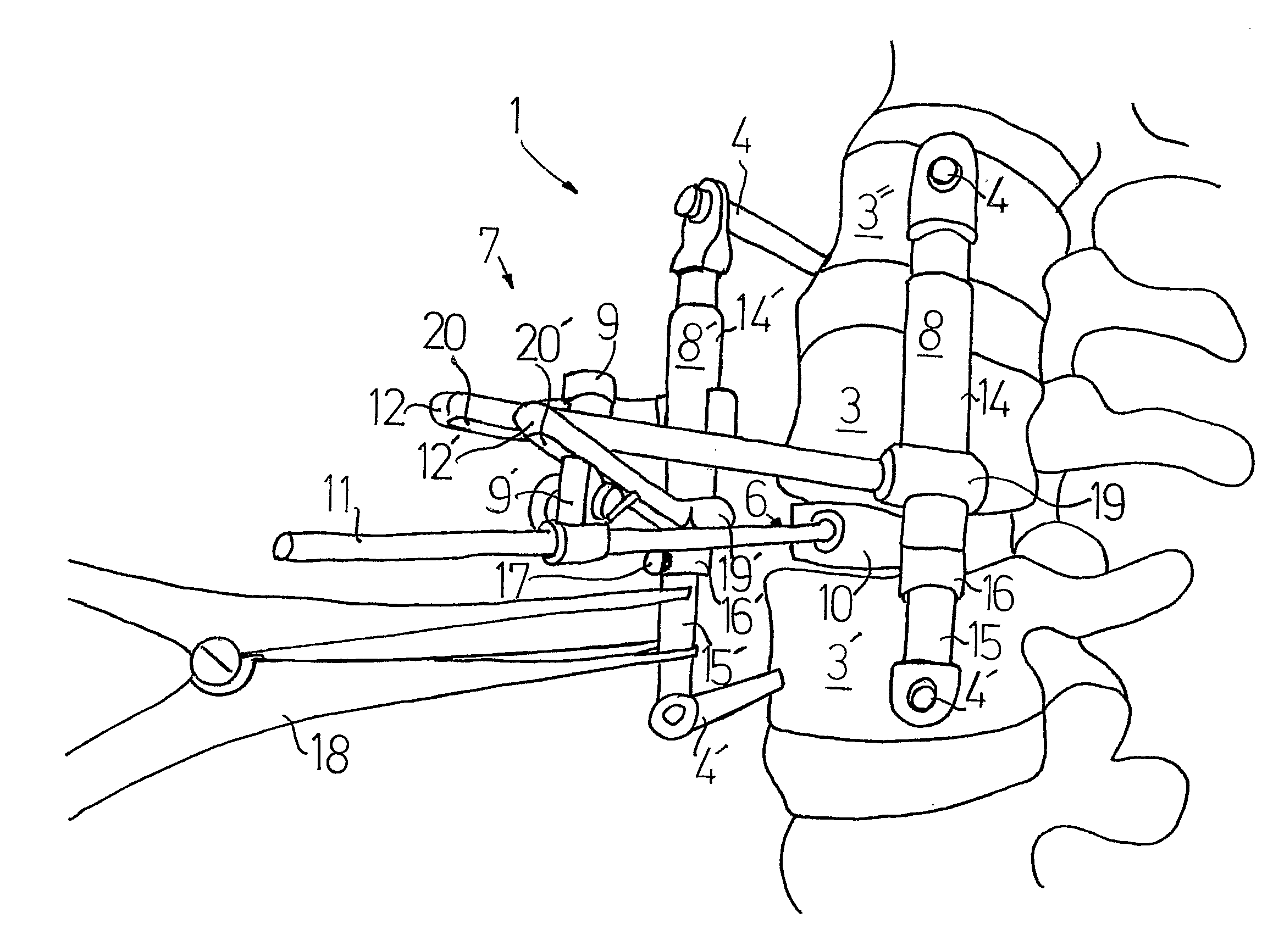
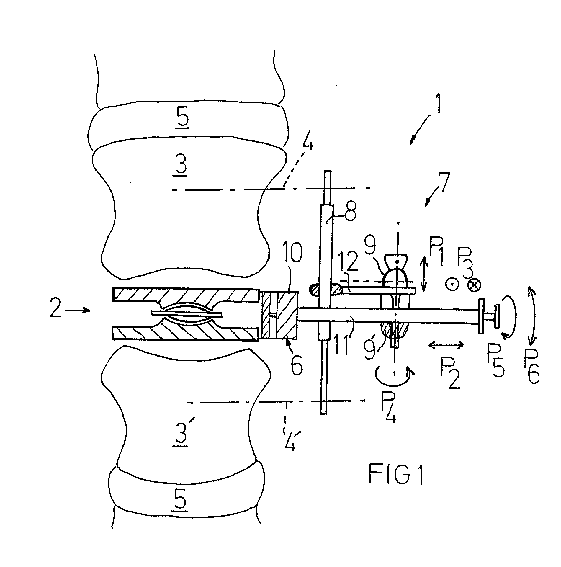
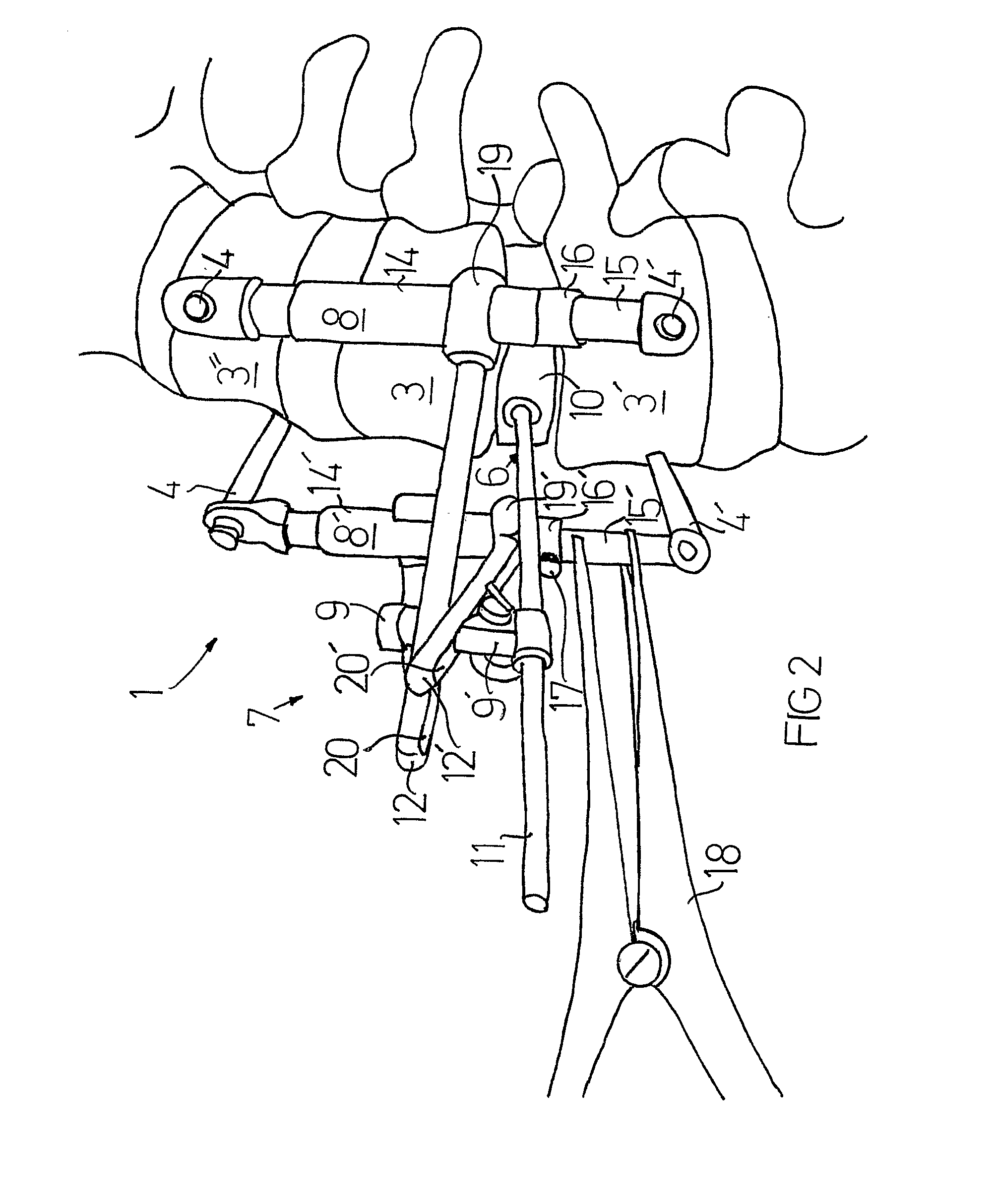
[0033]FIG. 1 shows a positioning device 1 in the process of positioning a disc implant 2 between two vertebrae 3 and 3′ in a spinal column of a living human being. With 5 are indicated two healthy discs, whereas between the vertebrae 3 and 3′ is cleared out all material from a damaged disc to be replaced by said disc implant 2.

[0034]The disc implant 2 is held by a holding device 6 including a fork-shaped head 10, which releasably grips around the disc implant 2 and a rod shaped manipulating element 11 which can be manipulated by hand by a surgeon.

In the embodiment shown in FIG. 1, the manipulating element 11 is controlled by a fixing means 7, which in turn is connected to the distance device 8 (only one shown on FIG. 1), which in turn over engagement means in the form of screws, (indicated with dash dotted lines, and with numerals 4 and 4′), is in engagement with two vertebrae 3, 3′.

[0035]The fixing means 7 includes fixing elements 12 (only one shown in FIG. 1) together with a unive...


PUM


Abstract

A positioning device (1) for placing a prosthesis device (2) in a spinal column of a living mammal, including at least one holding device (6) for cooperation with the prosthesis device and for guiding thereof during positioning, wherein it includes fixing means (7) for fixation with respect to at least one vertebra (3,3′), and said fixing means includes locking means (9), which in a first, free state, allows adjustment movement of said holding means (6) and thereby of the prosthesis device (2), and in a second, locked state, fixes said holding device (6) and thereby the prosthesis device (2) in a selected position. The invention also concerns a system.

Description

FIELD OF THE INVENTION[0001]The invention concerns a positioning device according to the preamble of claim 1 and a system for engagement with vertebrae in a spinal column including such a positioning device.BACKGROUND OF THE INVENTION[0002]For patients diagnosed disc degeneration, surgical operations are performed more and more often for released troubles. The most common operation for these patients today is still fusion, where an ossified connection of the vertebrae is obtained. Also metallic connection devices can be used. The movability then ceases between the vertebrae in question but the patient will become free from pain. As the patient becomes more active and movable, the segments above and below the fused region will, however, be subjected to greater strains. The risk of new symptoms from surrounding segments thereby increases.[0003]As an alternative to fusion, disc implants have been presented. A known disc prosthesis generally consists of two mutually articulated plates t...

Claims


Application Information

Patent Timeline
IPC IPC(8): A61B17/58A61F2/44
CPCA61B2017/0256A61F2/4425A61F2/4611A61F2002/30131A61F2002/30507A61F2002/3054A61F2002/4687A61F2002/4622A61F2002/4627A61F2002/4628A61F2220/0025A61F2230/0013A61F2002/30571A61F2/46
Inventor JOHANSSON, ERIKAXEN, NIKLASBOWALD, STAFFANOLERUD, SVENJACOBSEN, HANS
Owner ORTOVIVA AB
Why Eureka
Try Eureka