
Industrial Robot Tending A Machine And A Method For Controlling An Industrial Robot Tending A Machine

a technology of industrial robots and machines, applied in the direction of program control, total factory control, instruments, etc., can solve the problems of difficult to teach the robot motion, waste of valuable time, and difficult to predict if the robot can extract parts, etc., and achieve the effect of easy programming of the tending process

Inactive Publication Date: 2009-08-27
ABB TECH AG
View PDF7 Cites 14 Cited by
  • Summary
  • Abstract
  • Description
  • Claims
  • Application Information

AI Technical Summary

Benefits of technology

[0010]The object of the present invention is to provide an attractive solution to the above-mentioned problems, and to provide an easy programming of the tending process with the robot and the machine.
[0014]Although the robot controller plans the movement path of the machine part, the robot controller does not control the motion of the machine part. The planning of the actual motion of the machine part and the generation of control signals to the machine part is done in a separate machine controller. Thus, the invention makes it possible to coordinate the robot motion with the motion of the machine part, thereby reducing the cycle time, at the same time as the actual control of the motion of the machine is carried out by a separate machine controller, thereby achieving an accurate control of the motion of the machine part.
[0017]This present invention has significant improvements over existing methods in that it allows easy programming and a simpler and more reliable method to prevent the robot from colliding with the machine during the tending. Only a single position / speed signal is needed from the machine controller to the robot controller. This will save costs.
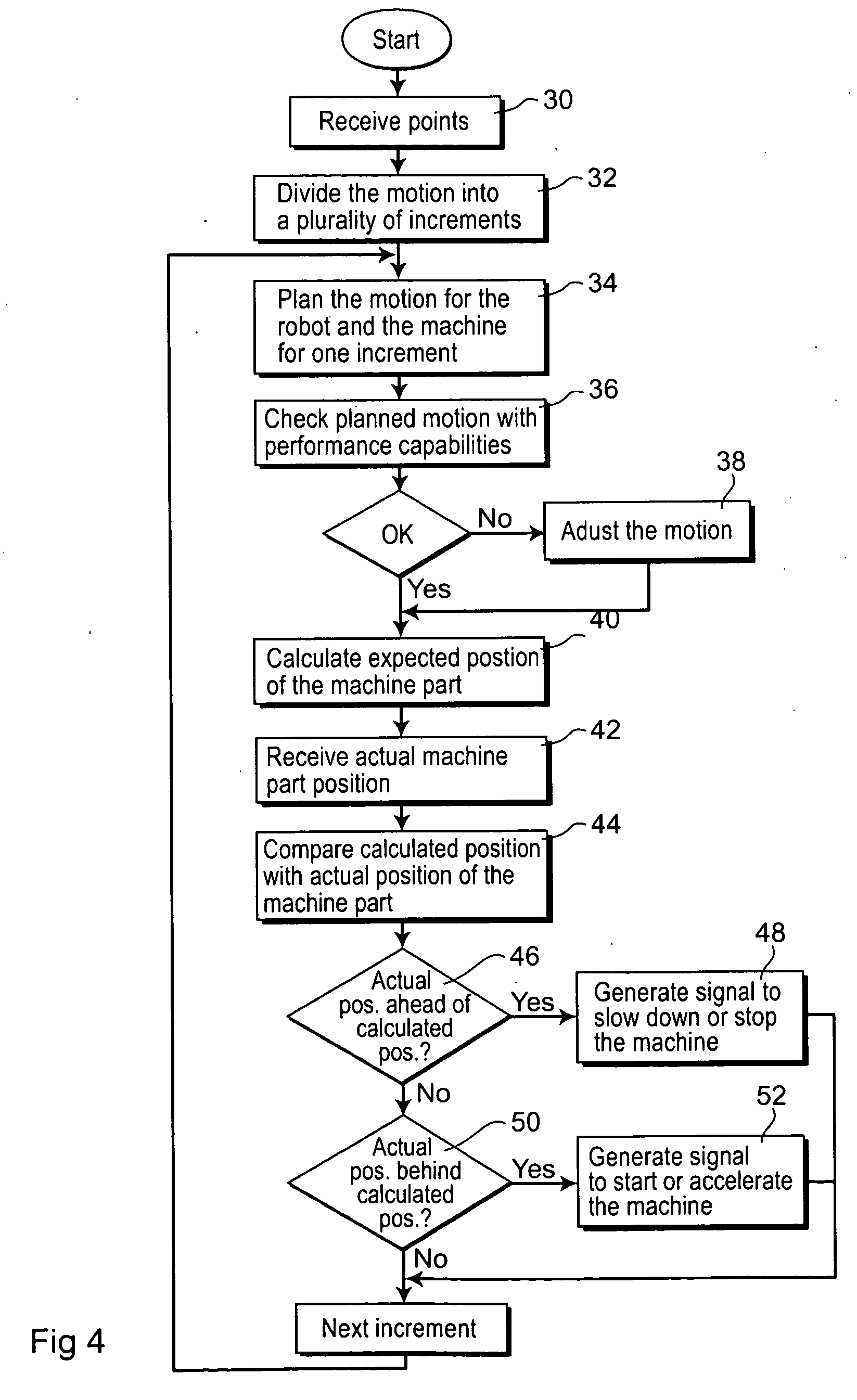
[0021]According to an embodiment of the invention, the robot controller further is configured to generate a signal to speed up the motion of the machine part when the actual position of the machine part is behind the expected positions of the machine part. This embodiment further reduces the cycle time.
[0022]According to an embodiment of the invention, the motion planner is configured to plan the motion of the robot and the machine part in incremental steps, and to calculate the expected position of the machine part for each incremental step, and the robot controller is configured, for each incremental step, to compare the actual position of the machine part with the expected position. As the motion planner plans the motion of the robot and the machine part in incremental steps, it is suitable to compare the actual position of the machine part with the expected position and generate the signal for slowing down or stop the motion of the machine part each incremental steps. Further, a high accuracy is achieved.
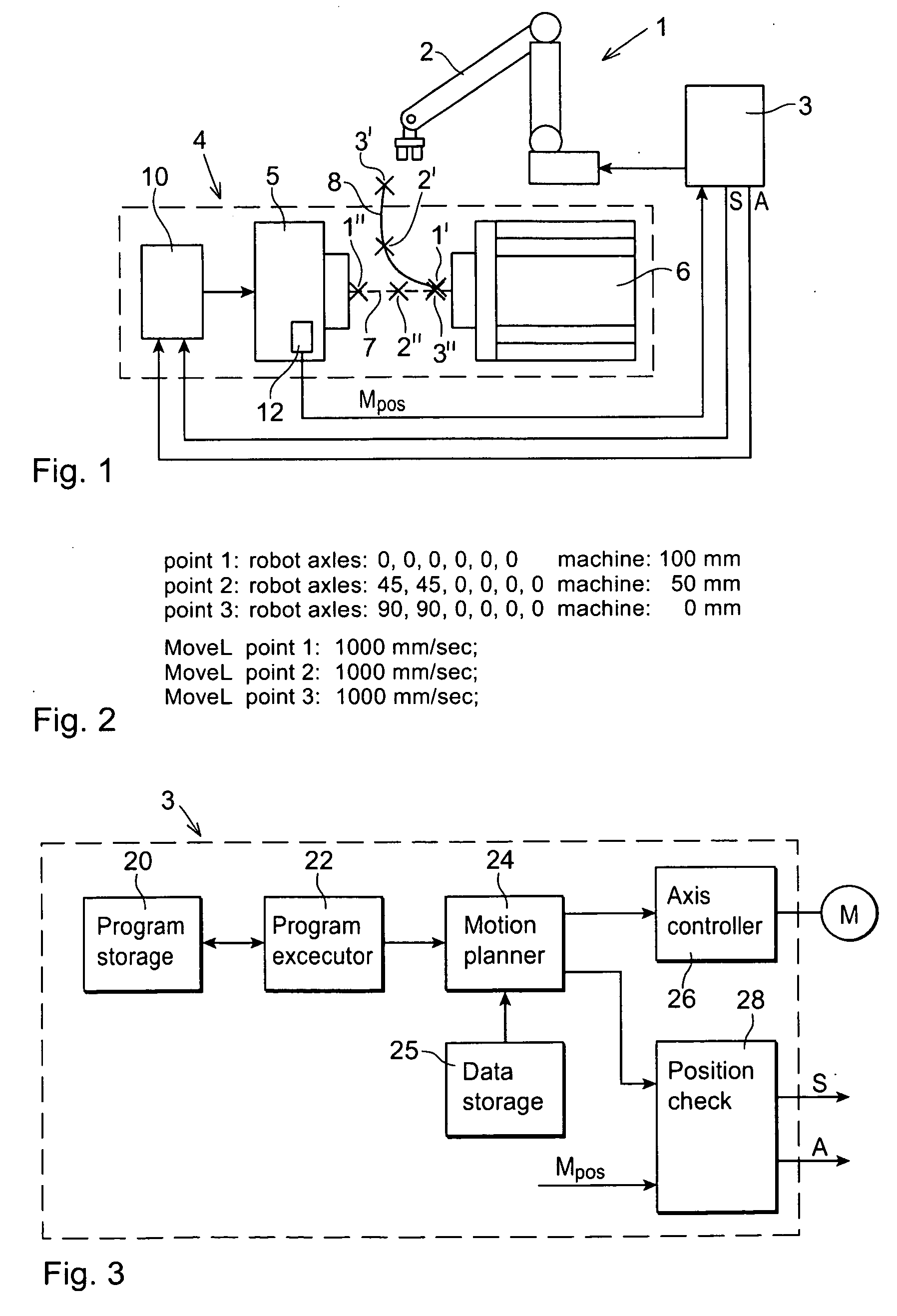
[0024]According to an embodiment of the invention, at least two of said programmed positions for the robot correspond in time to at least two of said programmed positions for the machine part. This means that the robot must be positioned in a programmed position on the robot path at the same point in time as the machine part is positioned in the corresponding programmed position on the machine path. Knowing the positions corresponding in time for the robot and for the machine part facilitates the coordination of the robot motion and the motion of the machine part.

Problems solved by technology

The problem that is faced is that once the robot has taken a part from the machine, the robot shall extract the part and itself from the machine at the same time that the machine is closing.
The problem is compounded in the fact that the machine is typically hydraulic and the closure is fast and not controlled by the robot controller.
It is normally very difficult to teach the robot motion and very hard to predict if the robot can extract the part without the mold hitting the robot during closure.
Therefore the waiting time consumes valuable time, and the cycle time of molding is prolonged.
The problem with this solution is that the calculation of the distance is complex and there are many points on the robot and the robot tool that could possibly collide with the closing mold.
However, for some machine parts, in particular if the actuator actuating the machine part is hydraulic, the control of the motion of the mold part is quite complicated, and therefore the robot controller is not suitable for controlling the machine part.
In addition, there may also be more complex motions and forces involved where a dedicated controller is optimal for the machine.
Thus a robot controller does not have functions and capacity to perform all necessary calculations for mold control.

Method used


Image

  • Industrial Robot Tending A Machine And A Method For Controlling An Industrial Robot Tending A Machine
  • Industrial Robot Tending A Machine And A Method For Controlling An Industrial Robot Tending A Machine
  • Industrial Robot Tending A Machine And A Method For Controlling An Industrial Robot Tending A Machine

Examples


Embodiment Construction

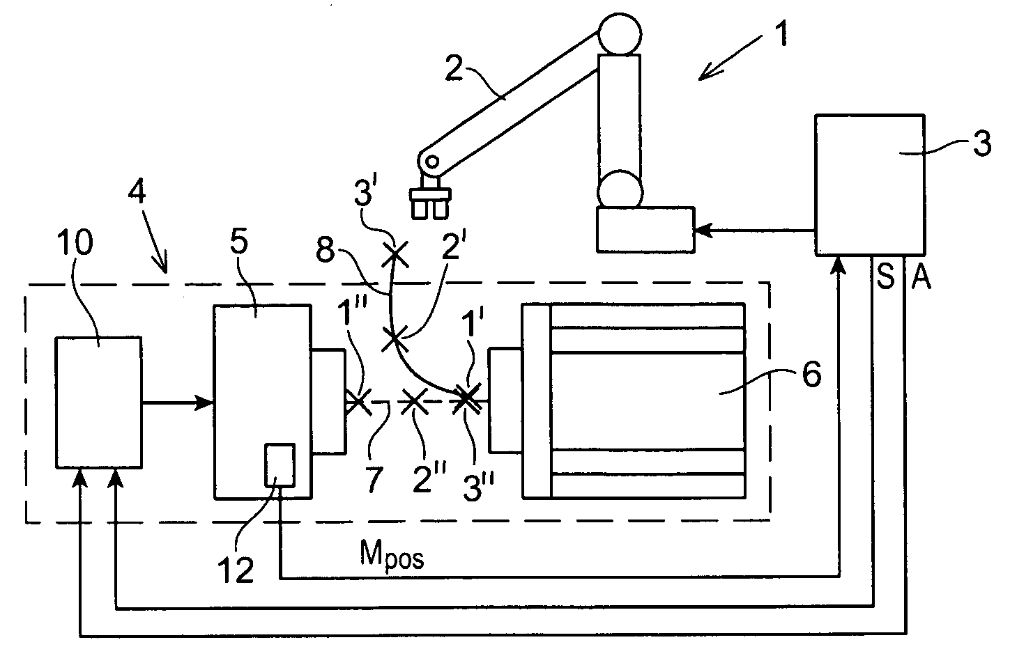
[0037]FIG. 1 shows an industrial robot 1 tending a machine 4 according to an embodiment of the invention. The industrial robot 1 includes a manipulator 2 movable about a plurality of axes and a robot controller 3 controlling the movements of the manipulator 2. The manipulator 2 includes a plurality of robot joints joined with each other so that they are rotatable or translatable relative to each other about a plurality of the axes. The robot 1 is provided with a tool, for example a gripper, adapted to pick the molded object from the machine 4 and to move it to another place for further processing. The tending of the machine may also include moving a workpiece to the machine and loading the machine with the workpiece. The manipulator includes a plurality of motors actuating the movements of the robot arms. The robot controller 3 includes an axis controller adapted to control signals, such as desired motor torques, to motors located in the manipulator 2. The control signals are genera...


PUM


Abstract

An industrial robot for tending a machine includes a machine part providing a repetitive sequence of movements. The robot includes a robot controller having a program storage for storing a path of programmed positions for the robot and a path of programmed positions for the machine part, and a motion planner configured to plan the motion of the robot and the motion of the machine part based on the programmed positions for the robot and the machine part such that the motion of the robot and the motion of the machine part are coordinated with each other.

Description

CROSS-REFERENCE TO RELATED APPLICATIONS[0001]The present application is a continuation of pending International patent application PCT / EP2007 / 061212 filed on Oct. 19, 2007 which designates the United States, the content of which is incorporated herein by reference.FIELD OF THE INVENTION[0002]The present invention relates to an industrial robot for tending a machine including a machine part providing a repetitive sequence of movements. The present invention also relates and to a method for tending such a machine.[0003]The present invention is suitable for any type of industrial process, which makes use of a machine that is tended by a robot, and the robot motion has to be coordinated with the motion of a movable part of the machine in order to avoid collisions between the robot and the machine part. Suitable processes are, for example, die casting, injection molding, and other types of metal forming and plastic machinery, loading and unloading of milling machines, lathes, grinding eq...

Claims


Application Information

Patent Timeline
Patent Type & Authority Applications(United States)
IPC IPC(8): G05B19/418
CPCG05B19/41825G05B2219/40498G05B2219/40054G05B2219/39105Y02P90/02
Inventor AUDIBERT, RAOUL
Owner ABB TECH AG
Learn More