Electronic component production method and electronic component production equipment

Inactive Publication Date: 2009-09-03
HARRIS CORP
View PDF53 Cites 10 Cited by
  • Summary
  • Abstract
  • Description
  • Claims
  • Application Information

AI Technical Summary

Benefits of technology

[0019]The converter unit, the press unit and the cutting unit are all units that handle the continuous base member. For this reason, the electronic component manufacturing apparatus can perform its work continuously and with high production efficiency by arranging each of the units in tandem.
[002

Problems solved by technology

However, the above-described conventional method of manufacturing an electronic component has the following problem.
Therefore, it is necessary to perform a base circuit sheet fabrication step, an interpo

Method used


Image

  • Electronic component production method and electronic component production equipment
  • Electronic component production method and electronic component production equipment
  • Electronic component production method and electronic component production equipment

Examples


Example

Embodiment 1

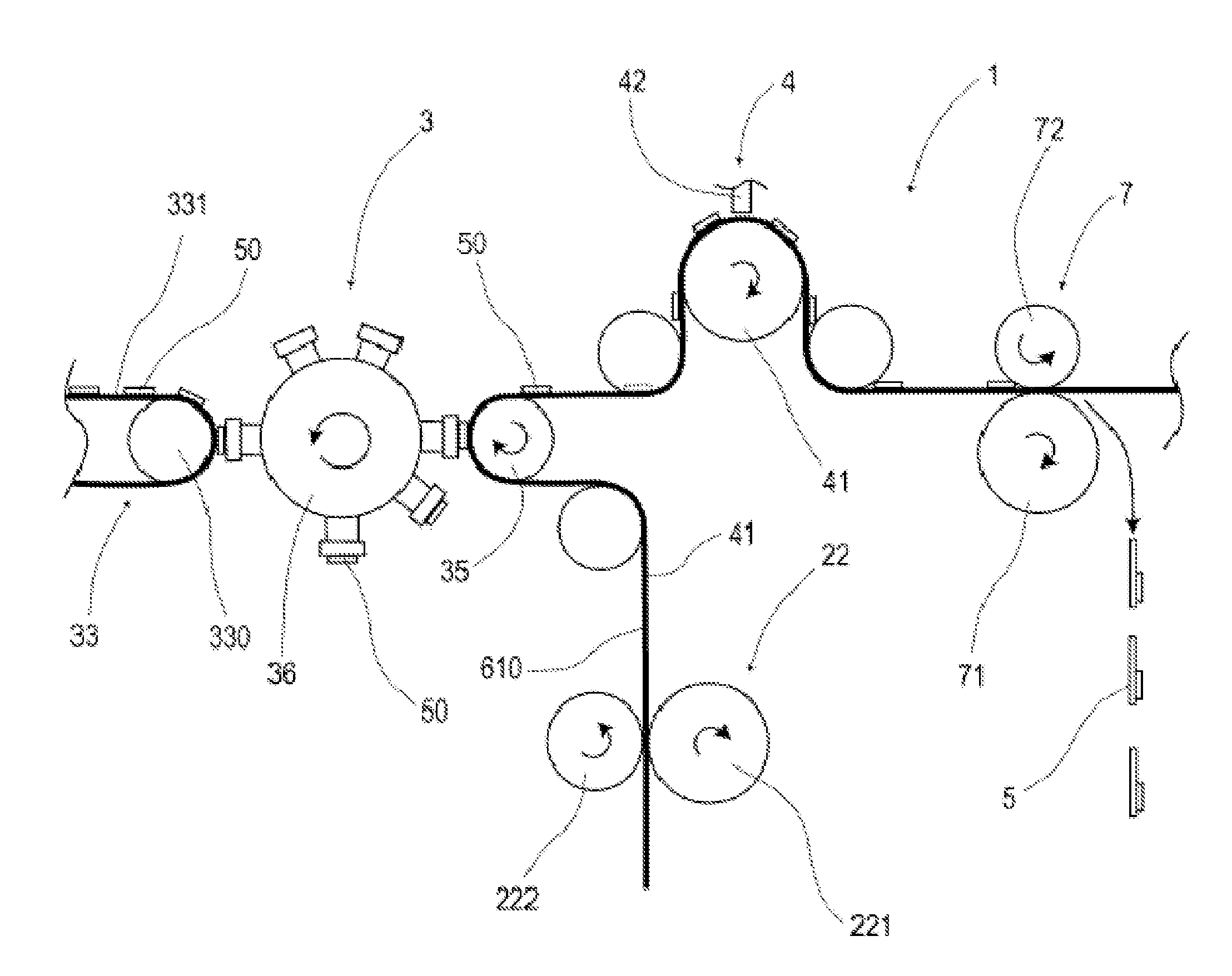
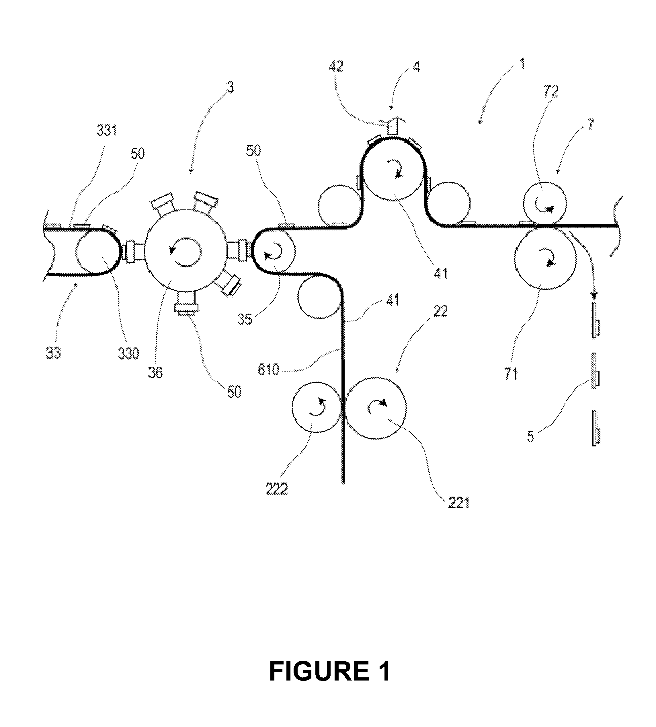
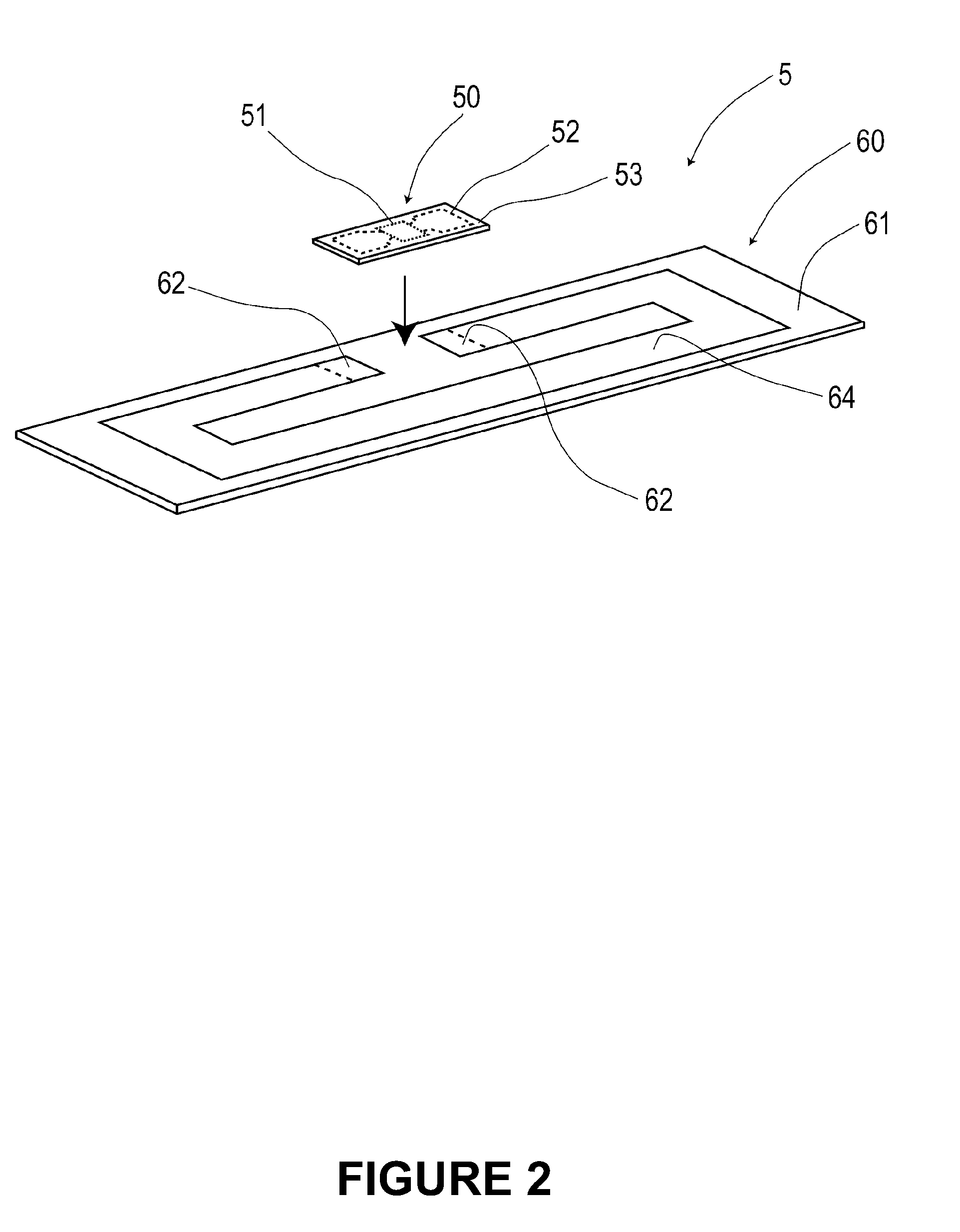
[0095]This embodiment relates to a method for fabricating an electronic component 5 including an interposer 50 in sheet piece form on which a semiconductor chip 51 is mounted. This embodiment will be described with reference to FIGS. 1 to 21.

[0096]As shown in FIGS. 1 and 2, the electronic component manufacturing method of this embodiment relates to an electronic component 5 in which an interposer 50, in which a semiconductor chip 51 is mounted on a sheet-like chip holding member 53 and which has an interposer-side terminal 52, which is a connection terminal provided in an extending manner from the semiconductor chip 51, is bonded to a base circuit sheet 60 that is formed from a sheet-like base member 61 and is provided, on a surface thereof, with a base-side terminal 62.

[0097]As shown in FIGS. 1 and 2, this electronic component manufacturing method includes a base circuit forming step for forming the base-side terminal 62 in a continuous base member 610 that is the base ...

Example

Embodiment 2

[0172]In this embodiment, a laminating step for laminating each RF-ID medium 5 is added on the basis of the electronic component manufacturing method of Embodiment 1. This embodiment will be described with reference to FIG. 22.

[0173]The electronic manufacturing apparatus 1 of this embodiment has a laminating unit 8 arranged in tandem on the downstream side of the step of the cutting unit 7. This laminating unit 8 laminates each of the RF-ID media 5, which are cut out from a continuous base member 610 by using a cutting unit 7, with resin films 810, 820.

[0174]The laminating unit 8 has a rotating roller 81 for holding and advancing the resin film 810 and a rotating roller 82 for holding and advancing the resin film 820. And in this laminating unit 8, the RF-ID medium 5 cut out by the cutting unit 7 is placed one by one on a laminating surface 811 of the resin film held by the rotating roller 81.

[0175]The rotating roller 82 and the rotating roller 81 substantially circumscr...


PUM

PropertyMeasurementUnit
Pressureaaaaaaaaaa
Speedaaaaaaaaaa
Circumferenceaaaaaaaaaa

Abstract

Manufacturing an electronic component 5 in which an interposer 50 is bonded to a base circuit sheet includes a base circuit forming step for forming a base-side terminal in a continuous base member 610 in continuous sheet form, an arranging/bonding step for arranging the interposer 50 on a surface of the continuous base member 610 in which the base-side terminal is formed and bonding the interposer 50, and a separating step for cutting out the electronic component 5 from the continuous base member 610 to which the interposer 50 is bonded. In this electronic component manufacturing method, for the common continuous base member 610, each of the steps is repeated in parallel while this continuous base material 610 is being advanced.

Description

TECHNICAL FIELD[0001]The present invention relates to a method for manufacturing an electronic component in which a sheet-like interposer, on which a semiconductor chip is mounted, is bonded to a sheet-like base circuit sheet and an apparatus for manufacturing an electronic component used in this manufacturing method.BACKGROUND ART[0002]For example, there have hitherto been available electronic components in which an interposer having a semiconductor chip mounted on a resin film is bonded to a surface of a sheet-like base circuit sheet formed from a resin film. Examples of such electronic components include an RF-ID medium in which an interposer having an IC chip mounted on a base circuit sheet is bonded to a base circuit sheet provided with an antenna pattern. In fabricating such an RF-ID medium, there is a case where, for example, an antenna sheet in individual-piece form provided with an antenna pattern is prepared beforehand and an interposer is bonded to the surface of this ant...

Claims


Application Information

Patent Timeline
IPC IPC(8): H05K3/10B23P19/00
CPCG06K19/07718G06K19/07749G06K19/07752Y10T29/4913H01L2924/14Y10T29/53174H01L2224/75822
Inventor AOYAMA, HIROSHINISHIGAWA, RYOICHI
Owner HARRIS CORP
Why Eureka
Try Eureka