Magnetostrictive torque sensor device, manufacturing method thereof, and vehicle steering apparatus

Active Publication Date: 2009-09-03
HONDA MOTOR CO LTD
View PDF7 Cites 11 Cited by
  • Summary
  • Abstract
  • Description
  • Claims
  • Application Information

AI Technical Summary

Benefits of technology

[0005]The present invention provides a magnetostrictive torque sensor device to improve detection precision by suppressing an eddy current occurring in a back-yoke and by stabilizing an alternating-current resistance of a coil in the case where the back-yoke is disposed in an outer periphery of a coil of the magnetostrictive torque sensor device.

Problems solved by technology

Since the back-yoke of the related-art magnetostrictive torque sensor device surrounds peripheries of the magnetization coil and the detection coil by 360°, an eddy current easily occurs, and thus a problem may arise in that the eddy current has a bad influence on detection precision.
Since a magnetic flux easily occurs at an edge of the back-yoke, when an edge shape of the back-yoke is irregular or a difference occurs in the edge shape, a problem may arise in that a difference in alternating-current resistance of the coil occurs.

Method used


Image

  • Magnetostrictive torque sensor device, manufacturing method thereof, and vehicle steering apparatus
  • Magnetostrictive torque sensor device, manufacturing method thereof, and vehicle steering apparatus
  • Magnetostrictive torque sensor device, manufacturing method thereof, and vehicle steering apparatus

Examples


first embodiment

[0034]Hereinafter, the invention will be described with reference to FIGS. 1 to 6.

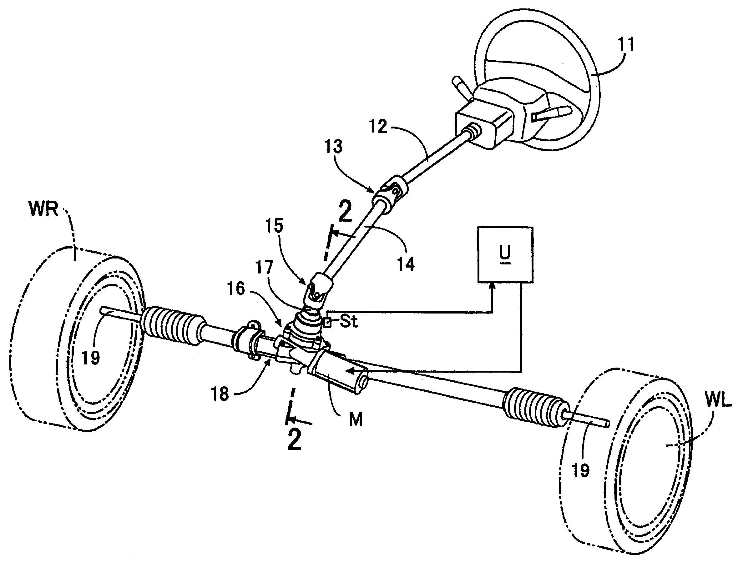
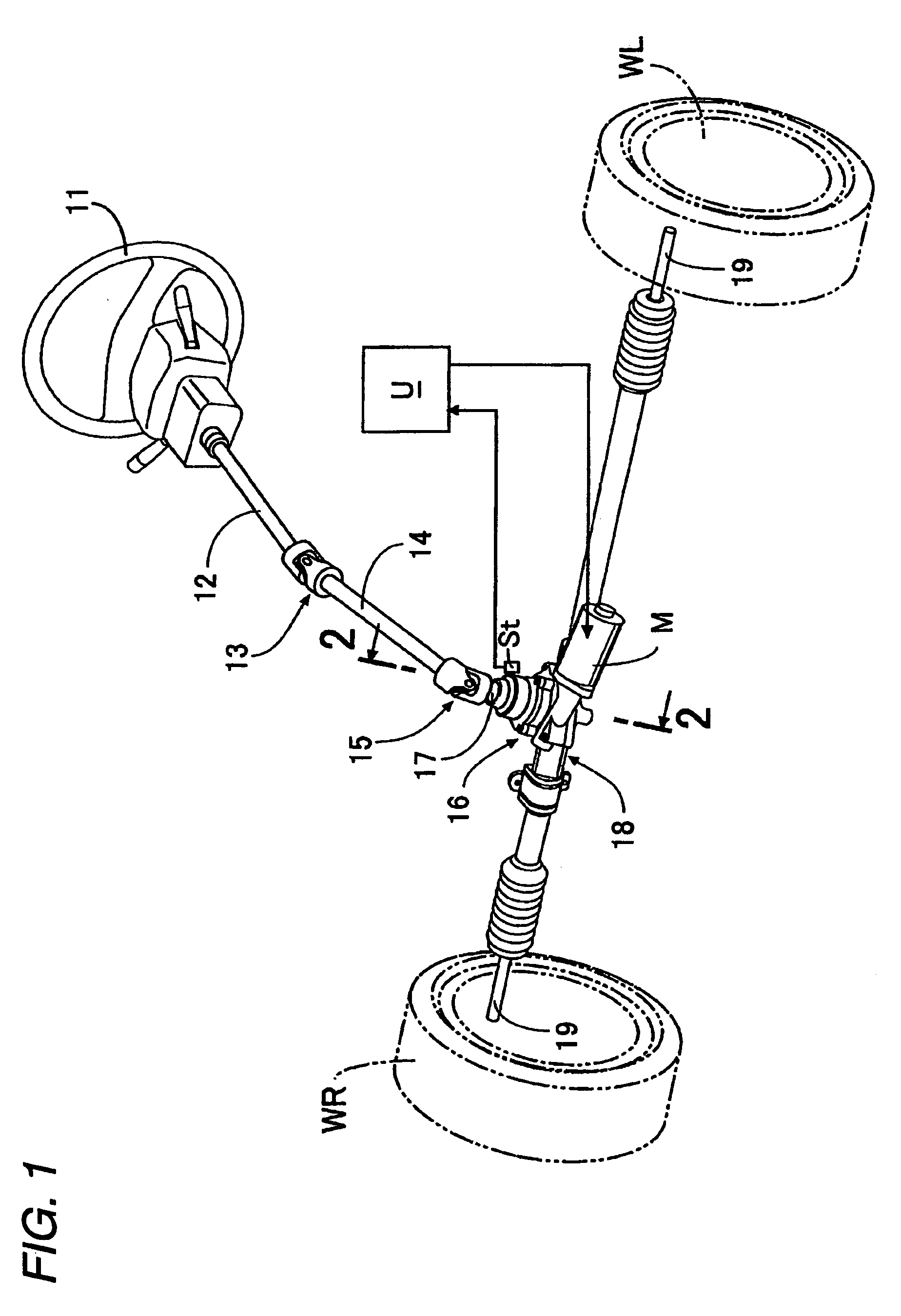
[0035]As shown in FIG. 1, an upper steering shaft 12 which rotates together with a steering wheel 11 is connected to a pinion shaft 17 which protrudes upward from a decelerator 16 via an upper universal joint 13, a lower steering shaft 14, and a lower universal joint 15. Tie-rods 19 which respectively protrude from both left and right ends of a steering gear box 18 connected to a lower end of the decelerator 16 are respectively connected to knuckles (not shown) of left and right vehicle wheels WL and WR. A motor M is supported to the decelerator 16, and an operation of the motor M is controlled by an electric control unit U which receives a signal from a steering torque sensor St received in the inside of the decelerator 16.

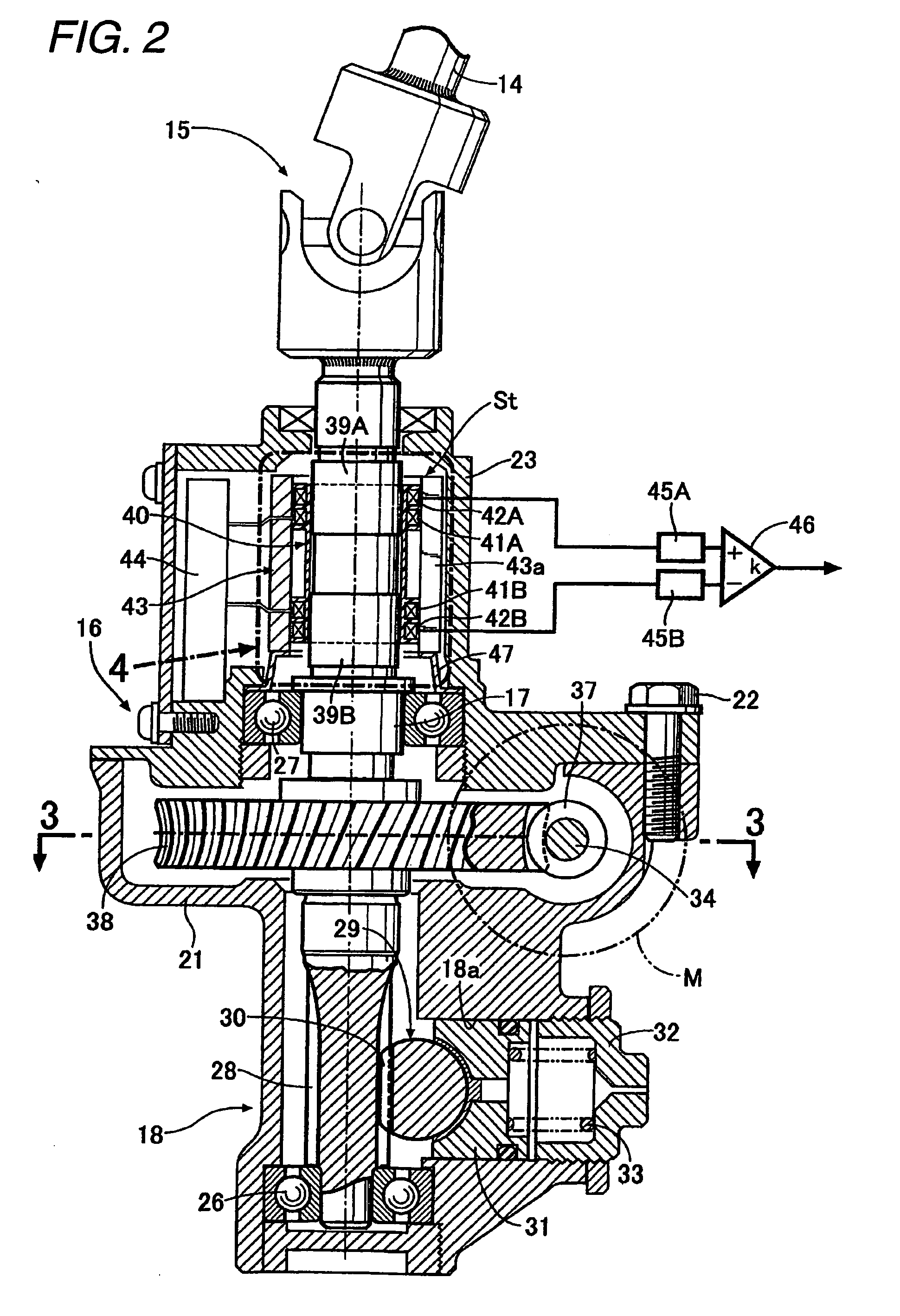
[0036]As shown in FIGS. 2 and 3, the decelerator 16 includes a lower case 21 which is integrally formed with the steering gear box 18 and an upper case 23 which is coupled to an upp...

second embodiment

[0048]Hereinafter, the invention will be described with reference to FIG. 7.

[0049]The second embodiment provides a steering torque sensor to further improve output gains of the first and second detection coils 42A and 42B in such a manner that yoke rings 48 and 48 formed by an annular plate member are respectively added to both axial ends of the back-yoke 43 according to the first embodiment so as to form a more efficient magnetic path. At this time, if axial end surfaces of the back-yoke 43 are directly brought into contact with inner surfaces of the yoke rings 48 and 48, respectively, the magnitude of magnetic permeability becomes unstable due to a difference in parallel degree or surface roughness of the contact portion, thereby deteriorating detection precision of the steering torque sensor St.

[0050]However, in the second embodiment, plate-shaped extension portions 40h and 40h having a predetermined thickness are formed in such a manner that the flanges 40b and 40g of both axial...

third embodiment

[0055]The back-yoke 143, the first and second yoke rings 148A and 148B, the first and second bobbins 140A and 140B, the first to fourth coils 141A to 141D, and the first and second terminal blocks 147A and 147B constitute a coil unit 149 according to the

[0056]Next, a forming process of the upper case 123, into which the coil unit 149 is integrally inserted, will be described with reference to FIGS. 11 to 17.

[0057]First, as shown in FIGS. 11 and 12, inner peripheral surfaces of the first and second bobbins 140A and 140B of the sub-assembly coil unit 149 are fitted to a cylindrical coil unit support portion 151a uprightly formed in a lower mold 151 of a die D. At this time, a rectangular-cylindrical slit fitting portion 151b uprightly formed in the lower mold 151 is fitted to a lower portion of the slit 143a of the back-yoke 143, that is, a portion lower than the second terminal block 147B.

[0058]Subsequently, as shown in FIGS. 13 to 15, traverse molds 152 and 153 are set to an upper p...


PUM

PropertyMeasurementUnit
Widthaaaaaaaaaa
Magnetostrictionaaaaaaaaaa
Torqueaaaaaaaaaa

Abstract

A magnetostrictive torque sensor device which detects a torque applied to a rotary shaft is provided. The magnetostrictive torque sensor device includes a magnetostrictive portion provided on a surface of the rotary shaft, a coil and a cylindrical back-yoke disposed in outer periphery of the coil. The coil includes a bobbin arranged in outer periphery of the magnetostrictive portion, and a wire wound around the bobbin. A slit is provided on the back-yoke.

Description

FIELD OF THE INVENTION[0001]The present disclosure relates to a magnetostrictive torque sensor device, a manufacturing method thereof which detects a torque applied to a rotary shaft by detecting a variation in a magnetic characteristic of a magnetostrictive film by means of a coil. Further, the present invention relates to a vehicle steering apparatus using the magnetostrictive torque sensor device as a steering torque sensor.DESCRIPTION OF RELATED ART[0002]The Japanese Patent Applications Laid-Open No. H11-132877 and No. 2007-292727 have disclosed examples of a related-art magnetostrictive torque sensor device for detecting a torque applied to a shaft. The magnetostrictive torque sensor device includes a pair of magnetostrictive films which is formed in an outer periphery of the shaft so as to have magnetic anisotropy opposite to each other. A magnetization coil and a detection coil which respectively surround outer peripheries of the magnetostrictive films. In the related art, a ...

Claims


Application Information

Patent Timeline
IPC IPC(8): B62D5/04G01L3/10H01F7/06
CPCG01L3/105Y10T29/49071G01L5/221G01L3/102
Inventor MIYOSHI, TAKASHIONIWA, YOSHIHIROSHIMIZU, YASUOYONEDA, ATSUHIKOARIMURA, YUTAKAWATANABE, KATSUJI
Owner HONDA MOTOR CO LTD
Why Eureka
Try Eureka