Brake rotor and abs tone ring attachment assembly that promotes in plane uniform torque transfer distribution

a technology of torque transfer and rotor, which is applied in the direction of braking discs, braking systems, transportation and packaging, etc., can solve the problems of thermal distortion of the rotor, replacement of the entire integrated assembly, and high cost and time consumption

Inactive Publication Date: 2009-09-03
PERFORMANCE FRICTION
View PDF15 Cites 66 Cited by
  • Summary
  • Abstract
  • Description
  • Claims
  • Application Information

AI Technical Summary

Benefits of technology

[0021]The invention is also directed to a brake assembly comprising a rotor having a braking surface and an attachment flange, wherein the attachment flange includes a plurality of spaced tabs, and a rotatable hub having an axial body, a mounting surface extending from the axial body for attachment to a vehicle component, and a rotor support extending from the axial body. The rotor support includes a radial surface that abuts the tabs of the rotor and a plurality of spaced bobbins. A plate is fastened to the bobbins to clamp each tab of the rotor between a pair of bobbins so as to cause torque generated during braking to transfer from the rotor tabs to the bobbins and the hub in a common plane. An anti-lock braking system is coupled to the brake assembly including a tone ring.

Problems solved by technology

A significant drawback, however, is that the assembly is constrained at the hub, which causes thermal distortion of the rotor.
Such thermal distortion can damage the rotor, and when the rotor is damaged or worn, the entire integrated assembly must be replaced.
This is expensive and time consuming.
Hat rotors, however, also have some drawbacks.
Rotor run-out causes excessive and uneven wear in the rotor braking surfaces and in brake pads which contact the rotor braking surfaces.
Rotor run-out also increases thermal distortion of the brake rotor.
The thermal distortion results in thermal judder, noise, and vibrations during braking, as well as causing irregular braking pulsations.
This can be a significant problem as it is very difficult to achieve perfect machining.
Another deficiency with hat rotor hub assemblies results from the manner in which a hat rotor and a wheel are mounted together on the hub.
However, if the wheel lug nuts are not evenly tightened, the uneven forces acting on the hub may result in the distortion of the hub.
Additionally, if the wheel rim has been improperly manufactured, the wheel rim might impose a distortion on the hub as the lug nuts are tightened.
During braking, the rotor in such an assembly is subjected to high frictional forces that generate heat in the rotor causing thermal expansion / distortion, temperature variation across the face of the rotor, and heat transfer to the adjacent components including the hub and the bearings.
Thermal expansion of the rotor is very limited, in the radial direction, because of the integral connection between the rotor and the hub.
This creates thermal coning in the rotor surface and a large thermal gradient, which will induce high thermal stress leading to thermal cracking.
The high thermal gradient generated during braking and the effects of the thermal expansion and distortion can cause vibration and thermal judder across the brake surfaces, resulting in rough or irregular braking pulsations.
The high thermal stress and thermal distortion also reduce the life and performance of the rotor and increase maintenance costs.
This creates twisting in the areas adjacent the fastener, which can create fatigue leading to cracking and breaking.
The perforated flange tends to become fatigued because the material of the rotor, cast iron for example, weakens at high temperatures leading to fatigue fractures.
This also creates problems with run-out, as discussed above, along with premature fracture of components in the connection.
Torque transfer also tends to be non-uniform through the perforated flange, especially in a floating design, as the machining tolerance at each aperture causes certain connections to receive more torque than other connections.
This creates high stresses at individual apertures and can cause the attachment flange to crack or to have portions break off.
The two-piece hat rotor assemblies discussed above also have drawbacks associated with the hat portion, which typically has slots that match with the perforations in the rotor attachment flange.
This twisting causes the edges of the bobbin, which are typically square to match the slot, to gouge the sides of the slots, thus damaging the slotted piece.
In summary, prior art brake rotors have suffered from problems associated with wear and material fatigue due to stresses induced during the braking process, particularly bending stresses caused during torque transfer and non-uniform transfer of torque caused by machining tolerances.

Method used


Image

  • Brake rotor and abs tone ring attachment assembly that promotes in plane uniform torque transfer distribution
  • Brake rotor and abs tone ring attachment assembly that promotes in plane uniform torque transfer distribution
  • Brake rotor and abs tone ring attachment assembly that promotes in plane uniform torque transfer distribution

Examples


first embodiment

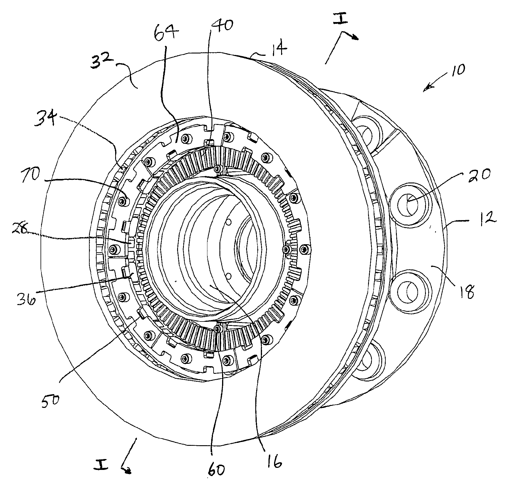
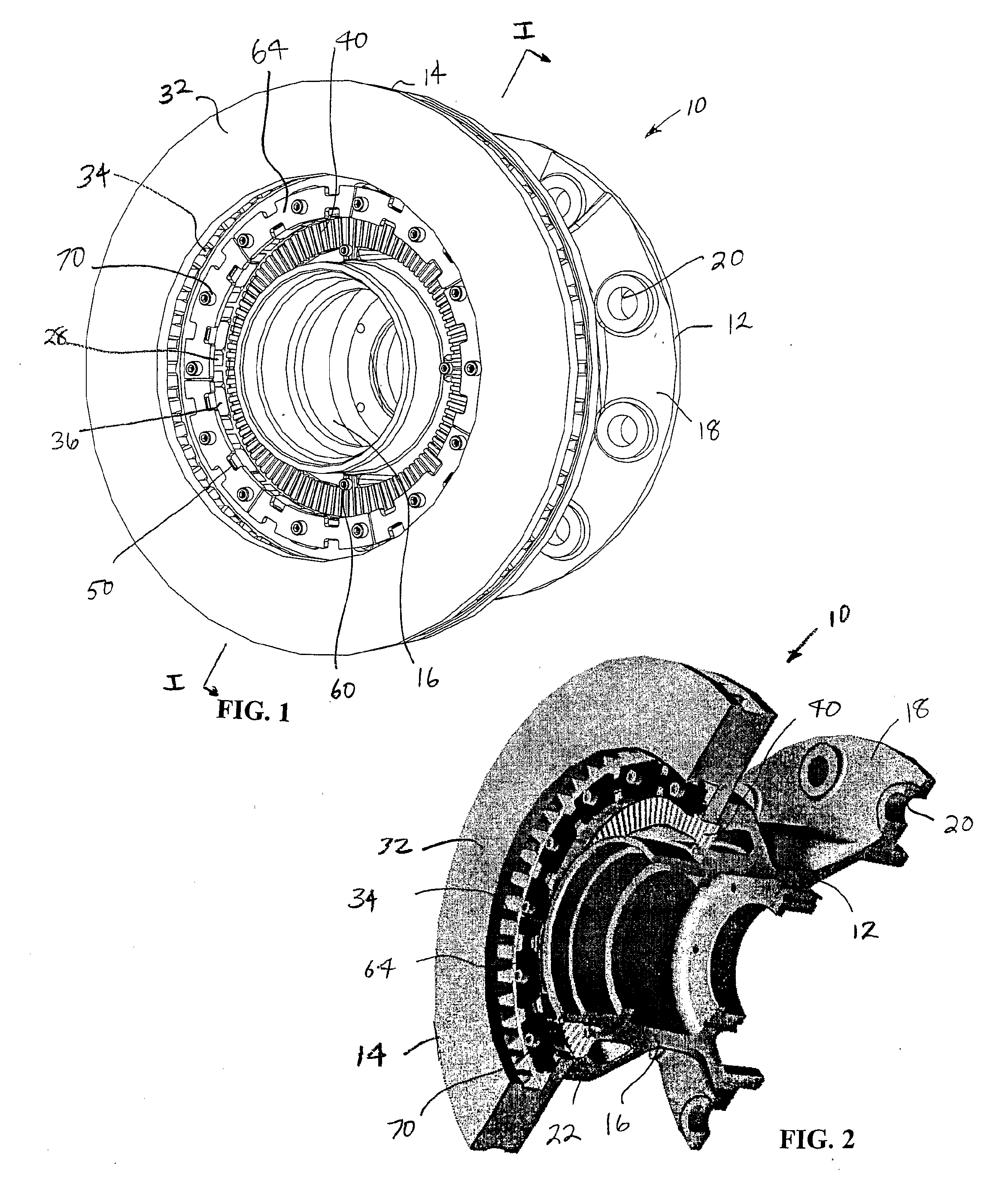
[0054]FIG. 1 shows a brake rotor assembly 10 in accordance with the invention. The assembly 10 includes a hub 12 that supports a rotor 14. The hub 12, as used herein, can be a wheel hub, a rotating flange, a bearing housing of a hub assembly or the hat portion of an integrated rotor. The term hub in this application is intended to cover all known possible mountings for a rotor.

[0055]The hub 12, seen in detail in FIGS. 3, 4, and 5, includes an axial body in the form of a central cylinder 16 with a radial mounting flange 18 on one end having a plurality of mounting apertures 20 therein and a rotor support flange 22 on the other end. The rotor support flange 22 extends outwardly from cylinder 16 and has an outward end that is radially spaced from the central cylinder 16. A series of axially extending threaded bores 21 are located on the central cylinder 16 in the space between the cylinder 16 and the flange 22. The outward end of the rotor support flange 22 is an annular ring that exte...

second embodiment

[0067]A second embodiment is shown in FIGS. 19-29, with FIG. 26 showing the entire assembly 100. In this embodiment, the tone ring and the top plate are formed as one structure to reduce the number of components needed and to simplify assembly. Referring to FIGS. 19-21, the difference between the hub 12 and the modified hub 102 is the rotor mounting flange. Hub 102 has a central cylinder 104 with a radial mounting flange 106 on one end having a plurality of mounting apertures 108 therein and a rotor support flange 110 on the other end. The rotor support flange 110 is spaced from the central cylinder 104. The rotor support flange 110 is an annular ring that extends around the central cylinder 104 with a series of spaced threaded apertures 112 and presents a radial face for mounting the rotor 14 thereon. An inner raised lip 114 is provided on the inner periphery of the flange 110. The same rotor 14 shown in FIG. 7 is used with this embodiment.

[0068]As seen in FIG. 22, the rotor 14 is ...


PUM


Abstract

A brake assembly for use on vehicles includes a rotor having connection tabs and a hub having bobbins, integrally formed or separate, with the rotor connection tabs being positioned between the hub bobbins and clamped together with a top plate. An ABS tone ring is fastened to the hub and is circumscribed by the rotor. Alternatively, an ABS tone ring can be formed as part of the top plate. A spring clip can be used with the top plate to accommodate thermal expansion of the rotor and eliminate rotor rattling. Torque is transferred from the brake rotor to the hub in a common plane to prevent twisting in the fastener connection.

Description

[0001]This application claims priority under 35 U.S.C. §119 from U.S. Provisional application No. 60 / 722,096 filed Sep. 30, 2005. The contents of this application are incorporated herein by reference.BACKGROUND OF THE INVENTION[0002]1. Field of the Invention[0003]The invention relates to brake assemblies, especially vehicular brakes including brake rotors attached to wheel hubs. This invention also relates to brake assemblies that include anti-lock braking systems (ABS).[0004]2. Description of Related Art[0005]One type of common prior art brake design for vehicles is a two piece hat rotor and hub in which a hat rotor that carries the braking surface is detachably connected to a wheel hub. Another common type of brake design is an integrated one-piece rotor and hub assembly.[0006]Integrated one-piece rotor and hub assemblies have the advantage that no fasteners are required between the rotor and the hub. As a result, the integrated assemblies do not face problems associated with fast...

Claims


Application Information

Patent Timeline
Patent Type & Authority Applications(United States)
IPC IPC(8): F16D65/12
CPCB60T8/329F16D65/12F16D2065/1396F16D2065/1384F16D2065/1392F16D2065/136F16D65/123F16D2065/1348
Inventor BURGOON, DONALDQIAN, WENQIPAUL, SCOTT ANDREWVAN HARKEN, CRAIG A.
Owner PERFORMANCE FRICTION
Why Eureka
Try Eureka