Hollow Fiber Membrane Module

a technology of hollow fiber membrane and membrane module, which is applied in the direction of membranes, filtration separation, separation processes, etc., can solve the problems of membrane breakage, filtration performance lowering, and filtration area reducing, so as to prevent the breakage of hollow fiber membrane, reduce the flux, and reduce the effect of chemical cleaning of hollow fiber membran

Active Publication Date: 2009-09-03
HAINAN LITREE PURIFYING TECH CO LTD
View PDF8 Cites 33 Cited by
  • Summary
  • Abstract
  • Description
  • Claims
  • Application Information

AI Technical Summary

Benefits of technology

[0008]The present invention has been made in view of the above problems in the prior art. It is therefore a first object of the present invention to provide a hollow fiber membrane module which can reduce breakage of hollow fiber membranes due to air bubbles remaining in the membrane module and can prevent lowering of the flux due to hollow fiber membranes becoming hydrophobic.
[0009]It is a second object of the present invention to provide a hollow fiber membrane module which has excellent physical cleanability, e.g., for air scrubbing as carried out when hollow fiber membranes are contaminated and which can perform stable filtration over a long period of time.
[0010]It is a third object of the present invention to provide a hollow fiber membrane module which can reduce the flow velocity of a fast flow of raw water and prevent breakage of hollow fiber membranes due to direct contact of the raw water with the hollow fiber membranes.

Problems solved by technology

In the hollow fiber membrane module having such a structure, however, there may occur a phenomenon (inter-fiber clogging phenomenon) of the formation of a rod-like bundle of hollow fiber membranes facing the circular holes, due to adhesion between the membranes in long-term use of the membrane module.
Thus, this phenomenon leads to decreased filtration area and lowered filtration performance.
Further, air bubbles are likely to remain in the hollow fiber membrane module, which can cause membrane breakage.
In particular, air bubbles are likely to remain in the upper end of the hollow membrane module upon air scrubbing, whereby an excessive stress is applied on the ends of the hollow membranes, causing breakage of the membranes at the ends.
It is highly likely that such remaining air bubbles will cause a similar phenomenon upon reverse cleaning using filtrate water.
Further, those portions of membranes on which air bubbles remain will dry and become hydrophobic.
Such a separation membrane module, however, necessitates a larger installation area as compared to a cylindrical membrane module having the same filtration area.
In addition, such a separation membrane module needs to use a large amount of cleaning chemical to clean contaminated membranes with a chemical, producing a large amount of chemical waste.
This is unfavorable also in the light of increased environmental burden.

Method used


Image

  • Hollow Fiber Membrane Module
  • Hollow Fiber Membrane Module
  • Hollow Fiber Membrane Module

Examples


example 1

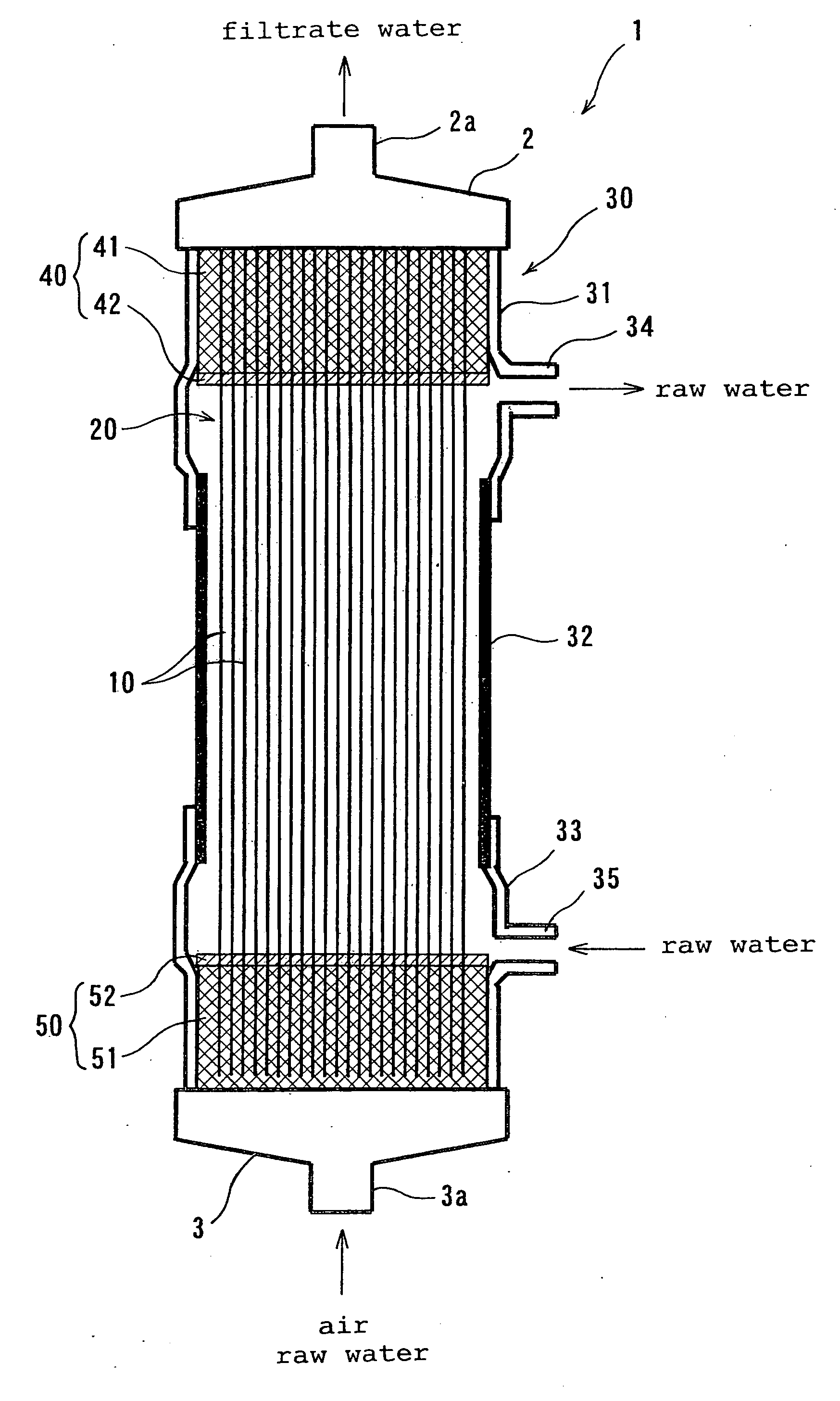
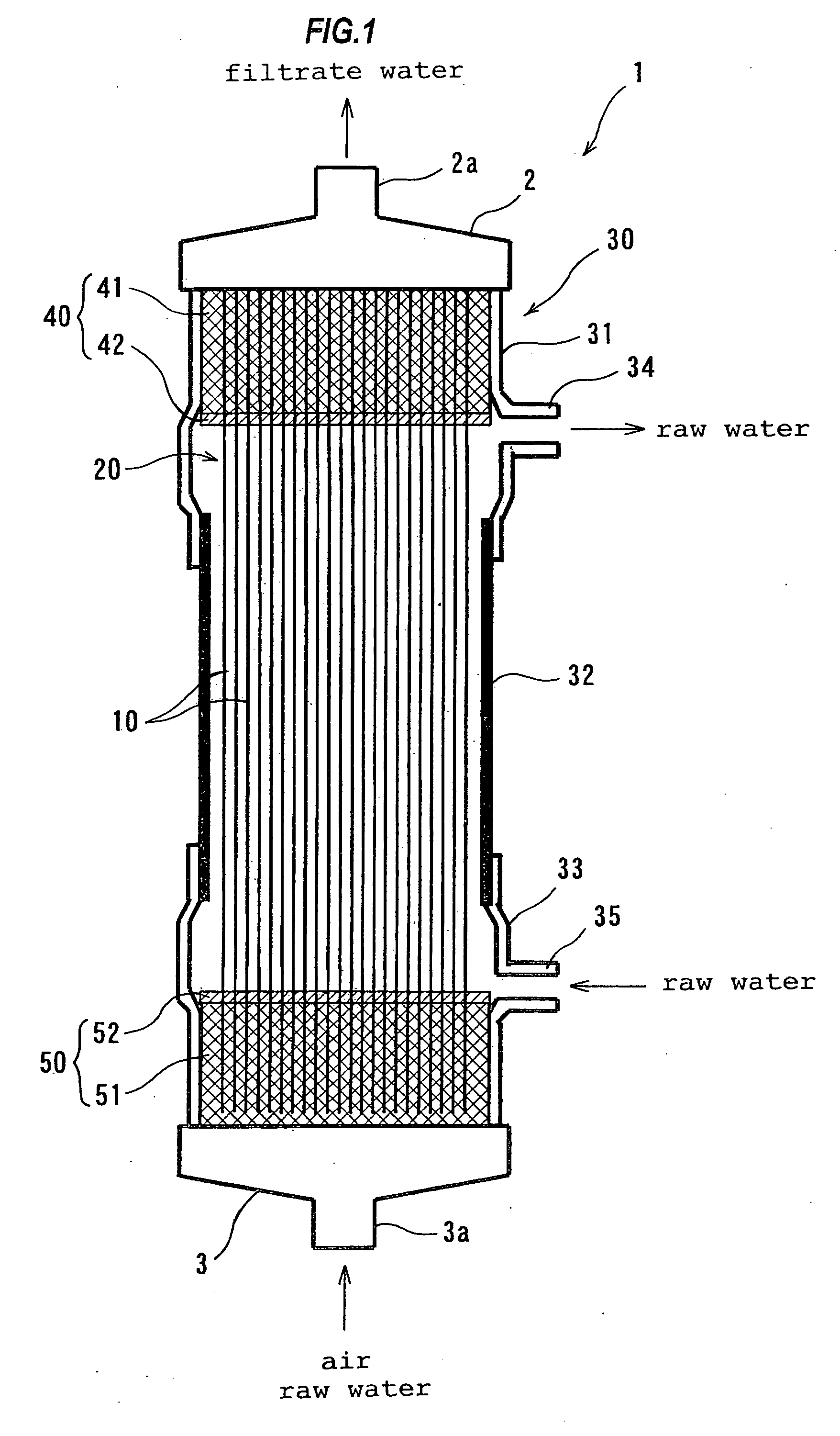
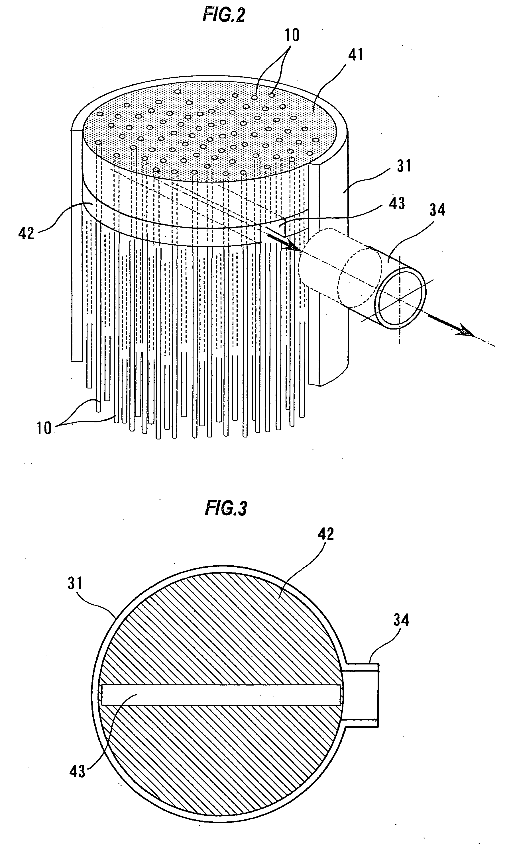
[0088]An experiment was conducted using a hollow fiber membrane module having the below-described construction. Porous hollow fiber membranes having a nominal pore size of 0.1 μm were used as the hollow fiber membranes 10, and a cylindrical pipe having an inner diameter of 150 mm was used as the intermediate casing 132. Porous structures were formed at both ends of the casing 132. A bundle of the hollow fiber membranes 10, the both ends of the bundle being fixed with a resin, was packed into a cylindrical body 130. A groove 43 having a width of 20 mm and a depth of 10 mm was formed in that area of the upper-end fixing portion 40 which makes contact with raw water. The groove 43 extends toward the raw water outflow nozzle 34 of the upper casing 31, as shown in FIG. 3.

[0089]Using the hollow fiber membrane module of the external-pressure type thus fabricated, the following normal-flow filtration test was conducted. First, filtration of raw water was carried out for 15 minutes by supply...

example 2

[0091]An experiment was conducted using a hollow fiber membrane module having the below-described construction. Porous hollow fiber membranes having a nominal pore size of 0.1 μm were used as the hollow fiber membranes 10, and a rigid polyvinyl chloride pipe having an inner diameter of 150 mm was used as the intermediate casing 132. Porous structures were formed at both ends of the casing 132. A bundle of the hollow fiber membranes 10, the both ends of the bundle being fixed with a resin, was packed into a cylindrical body 130. A groove 43 having a width of 20 mm and a depth of 10 mm was formed in that area of the upper-end fixing portion 40 which makes contact with raw water. The groove 43 extends toward the raw water outflow nozzle 34 of the upper casing 31, as shown in FIG. 3. Ten through-slits 53 having a width of 3 mm were formed in the resin fixing portion 51 and the soft potting portion 52 of the lower fixing portion 50, as shown in FIG. 5, so that air for air scrubbing as we...

example 3

[0094]An experiment was conducted using a hollow fiber membrane module having the below-described construction. Porous hollow fiber membranes having a nominal pore size of 0.1 μm were used as the hollow fiber membranes 10, and a rigid polyvinyl chloride pipe having an inner diameter of 150 mm was used as the intermediate casing 132. Porous structures were formed at both ends of the casing 132. A bundle of the hollow fiber membranes 10, the both ends of the bundle being fixed with a resin, was packed into a cylindrical body 130. A groove 43 having a width of 20 mm and a depth of 10 mm was formed in that area of the upper-end fixing portion 40 which makes contact with raw water. The groove 43 extends toward the raw water outflow nozzle 34 of the upper casing 31, as shown in FIG. 3. Ten through-slits 53 having a width of 3 mm were formed in the resin fixing portion 51 and the soft potting portion 52 of the lower fixing portion 50, as shown in FIG. 5, so that air for air scrubbing as we...


PUM

PropertyMeasurementUnit
depthaaaaaaaaaa
depthaaaaaaaaaa
widthaaaaaaaaaa

Abstract

There is provided a hollow fiber membrane module (1) comprising: a membrane bundle (20) of a plurality of hollow fiber membranes (10); a cylindrical body (30) housing the membrane bundle (20); a fixing portion (40, 50) in which at least one end of the membrane bundle (20) is fixed to the cylindrical body (30); and a raw water outflow nozzle (34) for allowing raw water to flow out from the vicinity of the fixing portion (40). Raw water supplied into the cylindrical body (30) is allowed to permeate from the outside into the inside of each hollow fiber membrane (10). A soft potting portion (42) has, in its surface to be in contact with raw water, at least one groove (43).

Description

TECHNICAL FIELD[0001]The present invention relates to a hollow fiber membrane module, and more particularly to a hollow fiber membrane module for use in the purification of clean water, drinking water, industrial water, pure water, or the like, in the clarification of river water, seawater, or the like, in the treatment of various types of wastewater, human waste, sewage water, or the like, and in a water treatment, such as slurry condensation, of sludge or the like.BACKGROUND ART[0002]A membrane separation method, which involves allowing water to be treated to permeate through a separation membrane to remove components or particles from the water, is widely used in many fields, for example, in the purification of clean water, drinking water, industrial water, pure water, or the like, in the clarification of river water, sea water, or the like, in the treatment of various types of wastewater, human waste, sewage water, or the like, and in a water treatment, such as slurry condensati...

Claims


Application Information

Patent Timeline
Patent Type & Authority Applications(United States)
IPC IPC(8): B01D63/02C02F1/44
CPCB01D63/02B01D63/022C02F1/444B01D2313/08B01D2313/10B01D2313/04
Inventor SAKASHITA, DAICHIKAIYA, YOSHIHIDEOBA, MASAZUMIFUTAMI, KENICHIHAYAKAWA, JUNICHICHEN, LIANGGANGCHEN, QING
Owner HAINAN LITREE PURIFYING TECH CO LTD
Why Eureka
Try Eureka