Light guide and image reader

a technology of image reader and light guide, which is applied in the field of light guide, can solve the problems of color unevenness, increase of cost and dispersion of characteristics of light scattering pattern, etc., and achieve the effects of avoiding color unevenness, reducing manufacturing cost, and preventing the reduction of the amount of light emitted

Active Publication Date: 2009-09-03
NIPPON SHEET GLASS CO LTD
View PDF2 Cites 27 Cited by
  • Summary
  • Abstract
  • Description
  • Claims
  • Application Information

AI Technical Summary

Benefits of technology

[0020]According to the present invention, the light scattering patterns formed on the side of the light guide are made into concavo-convex shape which can be formed at the time of forming the light guide, thereby enabling the manufacturing cost to be reduced. The light scattering patterns near the incident end face, in particular, are made independent of an angular dependence, thereby allowing avoiding a color unevenness which emphasizes specific colors at the vicinity of the incident face. In addition, the light scattering patterns away from the incident end face are made angle dependent, thereby enabling preventing reduction in amount of light emitted from the light-emitting surface.

Problems solved by technology

A method of printing above described white pigment to form the light scattering patterns requires a printing process which causes the increase of cost and the dispersion of characteristics of the light scattering patterns.
Thus, the extraordinary light intensity of specific colors, for example, the blue (B) and the red (R) in the vicinity of a main-scanning displacement of 15 mm emphasizes the blue (B) and the red (R) in the vicinity of a main-scanning displacement of 15 mm, resulting in unevenness in color.

Method used


Image

  • Light guide and image reader
  • Light guide and image reader
  • Light guide and image reader

Examples


Embodiment Construction

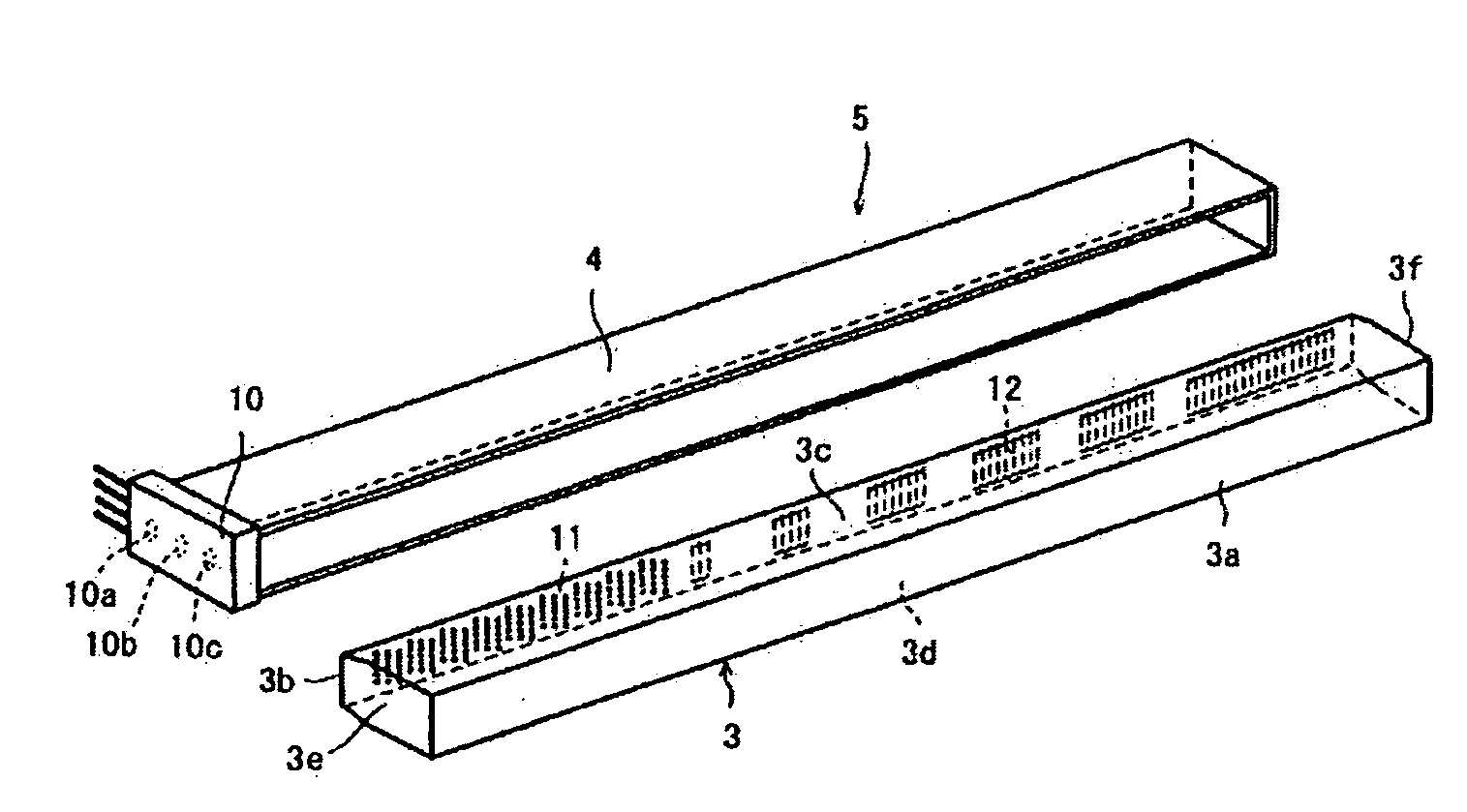
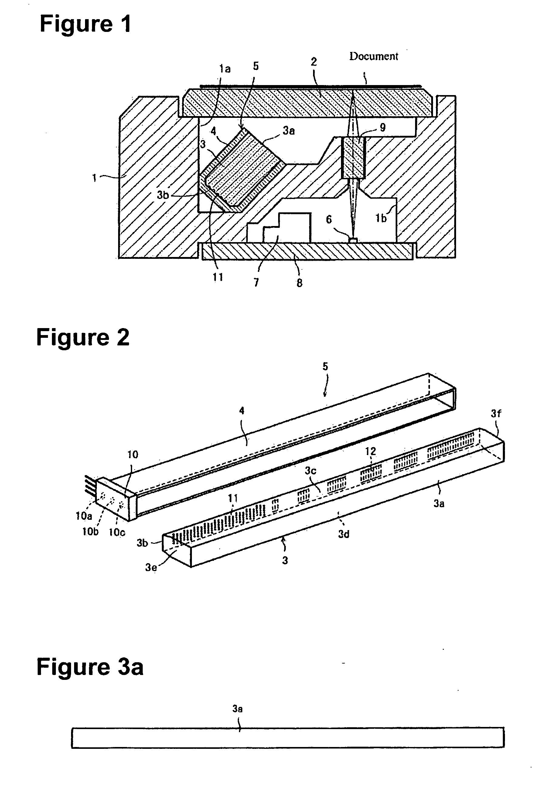
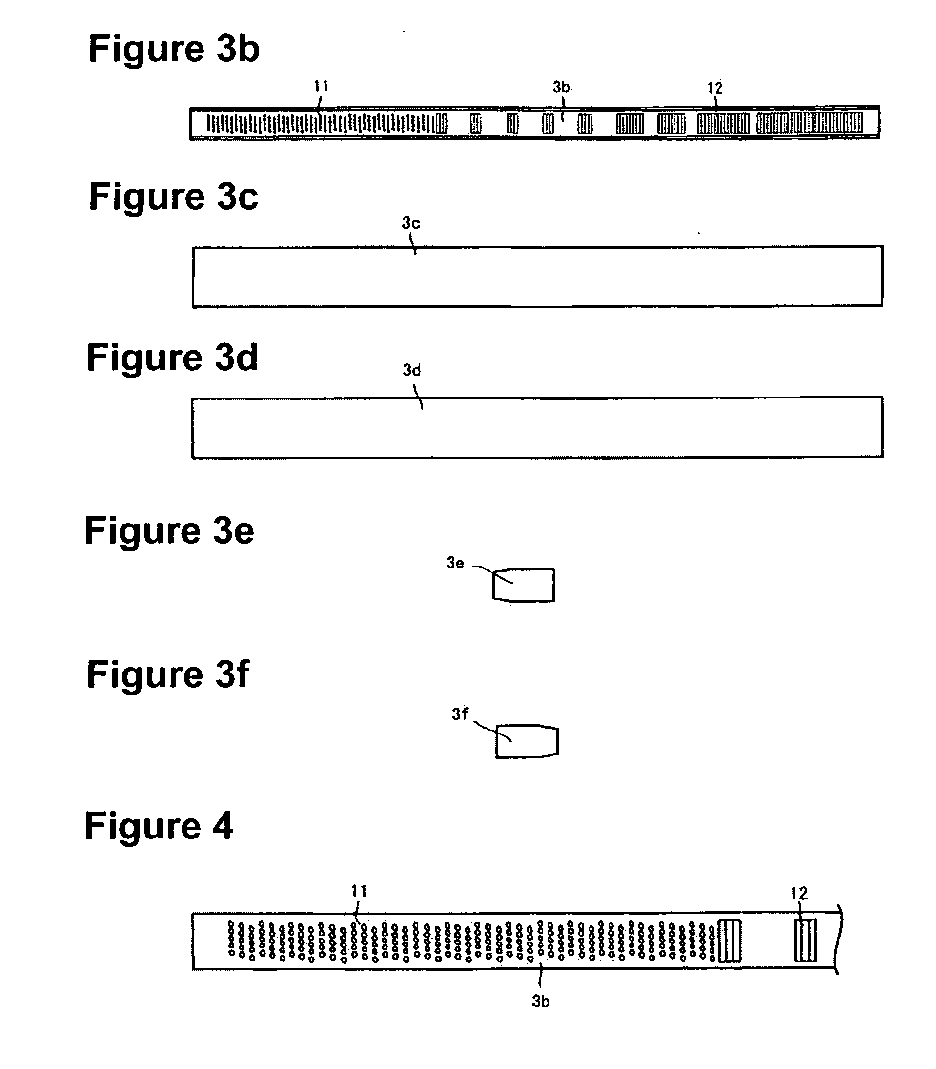
[0021]The embodiment of the present invention is described below with reference to accompanying drawings. FIG. 1 is a cross section of an image reader using a line illuminating device incorporating the light guide according to the present invention. FIG. 2 is an exploded perspective view of the line illuminating device. FIG. 3(a) is a front view of the light guide according to the present invention, FIG. 3(b) is a rear elevation view thereof, FIG. 3(c) is a top view thereof, FIG. 3(d) is a bottom view thereof, FIG. 3(e) is a left side view thereof and FIG. 3(f) is a right side view thereof. FIG. 4 is an enlarged view of the light scattering patterns in the vicinity of the incident face of the light guide according to the present invention.

[0022]The image reader is configured such that concave portions 1a and 1b are formed in a frame (housing) 1, the upper face of the concave portion 1a is covered with a transparent top plate 2 on which a document is placed, a line illuminating devic...


PUM


Abstract

A rod-shaped light guide which does not cause unevenness in color at the portion near an incident face is produced by injection-molding transparent resin such as acryl and its surfaces include a light-emitting surface, a bottom face, left and right sides and end faces. One end face opposes a light emitting unit, and light scattering patterns for scattering light incident from the end face are formed on the bottom face. The light scattering patterns are different in shape between a portion near the end face as the incident face and a portion away from the end face. The light scattering patterns formed at the portion near the incident face are composed of a large number of fine hemispherical concaves, whereas the light scattering patterns at the portion away from the incident face are composed of triangular grooves or half cylindrical grooves, and the axial direction of these triangular grooves or half cylindrical grooves is equal to coincides with the width direction (sub-scanning direction) of the bottom face on which the patterns are formed.

Description

TECHNICAL FIELD[0001]The present invention relates to a light guide used for an image reader and an image reader with the light guide.BACKGROUND ART[0002]An image reader such as a facsimile, a copying machine, an image scanner or the like is provided with a illuminating device incorporating a rod-like light guide illuminating linear light on a document surface and a image sensor with a lens array focusing light reflected from the document surface on a line image sensor.[0003]The illuminating device incorporating the rod-like light guide is configured such that light emitting means such as an LED is provided on one end of the rod-like light guide, light from the light emitting means is introduced from its end face into the inside, light propagating inside the rod-like light guide is scattered by light scattering patterns formed on the side of the rod-like light guide and scattered light is illuminated on the document surface from the light-emitting surface of the rod-like light guide...

Claims


Application Information

Patent Timeline
Patent Type & Authority Applications(United States)
IPC IPC(8): H04N1/04F21V8/00
CPCG02B6/0036H04N2201/03183G03B27/54H04N1/02815H04N1/02835H04N1/02885H04N1/0289H04N1/0318H04N2201/02487H04N2201/03112H04N2201/03125H04N2201/03129H04N2201/03141H04N2201/03145G02B6/0038H04N1/028H04N1/04
Inventor IKEDA, MAKOTONEMOTO, HIROYUKIKISHIMOTO, TAKASHIISHIMARU, TAKESHIIWASE, HIROHIKOTAKEUCHI, HIDEMITSUSAITO, TOMIHISA
Owner NIPPON SHEET GLASS CO LTD
Why Eureka
Try Eureka