Climate control systems and devices for a seating assembly

a technology of climate control system and seat assembly, which is applied in the field of climate control, can solve the problems of seat occupants' back and other pressure points being sweaty, hot and uncomfortable for a long time, and problems that have been experienced with existing climate control system for seats, so as to reduce manufacturing costs, reduce or eliminate modifications to existing seat designs, the effect of easy installation

Inactive Publication Date: 2009-09-03
AMERIGON INC
View PDF98 Cites 157 Cited by
  • Summary
  • Abstract
  • Description
  • Claims
  • Application Information

AI Technical Summary

Benefits of technology

[0027]The disclosed climate controlled seat assembly can lead to decreased manufacturing costs. The seat bite line duct is easy to install and may reduce or eliminate modifications

Problems solved by technology

For example, an automotive vehicle exposed to the summer weather, especially where the vehicle has been parked in an unshaded area for a long period of time, can cause the vehicle seat to be very hot and uncomfortable for the occupant for some time after entering and using the vehicle, even with normal air conditioning.
Furthermore, even with normal air-conditioning, on a hot day, the seat occupant's back and other pressure points may remain sweaty while seated.
This is particularly true where a typical vehicle heater is unlikely to quickly warm the vehicle's interior.
There are, however, problems that have been experienced with existing climate control systems for seats.
For example, some climate control systems ar

Method used


Image

  • Climate control systems and devices for a seating assembly
  • Climate control systems and devices for a seating assembly
  • Climate control systems and devices for a seating assembly

Examples


Embodiment Construction

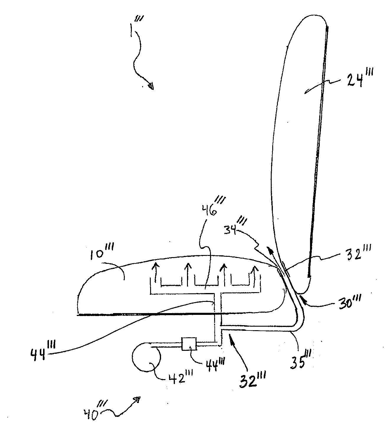
[0052]The climate control devices disclosed herein, as well as the various systems and features associated with them, are described in the context of a thermally conditioned seating assembly because they have particular utility in this context. However, the climate control devices, systems and methods described herein, or equivalents thereof, can be used in other contexts as well, such as, for example, but without limitation, other devices or systems where thermally-conditioned fluids are desired or required, electronic or other components where thermal conditioning is desired or required and / or the like.

[0053]To assist in the description of the disclosed embodiments, words such as up, upward, upper, top, down, downward, lower, bottom, vertical, horizontal, upstream, downstream and the other directional, direction-indicating words and / or the like are used to describe the accompanying figures. However, the illustrated embodiments can be located, configured and / or oriented in a variet...


PUM


Abstract

According to some embodiments disclosed in the present application, a climate control device configured for use with a seating assembly includes a fluid module having a fluid transfer device. The climate control device further comprises a fluid duct in fluid communication with the fluid module, wherein the fluid duct includes a distal end. The additional includes at least one outlet opening positioned at the distal end of the fluid duct. In some arrangements, the fluid duct is configured to be positioned at, near or through a seat bite area of the seating assembly. In other arrangements, the fluid module is configured to selectively transfer air to or from the at least one outlet opening through the fluid duct.

Description

CROSS-REFERENCE TO RELATED APPLICATIONS[0001]This application claims the priority benefit under 35 U.S.C. § 119(e) of U.S. Provisional Application No. 61 / 031,625, filed Feb. 26, 2008, the entirety of which is hereby incorporated by reference herein.BACKGROUND[0002]1. Field of the Inventions[0003]This application relates to climate control, and more specifically, to climate control of a seat assembly.[0004]2. Description of the Related Art[0005]Temperature modified air for environmental control of living or working space is typically provided to relatively extensive areas, such as entire buildings, selected offices, or suites of rooms within a building. In the case of vehicles, such as automobiles, the entire vehicle is typically cooled or heated as a unit. There are many situations, however, in which more selective or restrictive air temperature modification is desirable. For example, it is often desirable to provide individualized climate control for an occupant seat so that substa...

Claims


Application Information

Patent Timeline
IPC IPC(8): B60N2/56B60H1/00A47C7/74
CPCB60N2/5657A47C7/74
Inventor WOLAS, SCOTT R.
Owner AMERIGON INC
Why Eureka
Try Eureka