Polarization coupling cube-corner retro-reflectors

a cube-corner and retro-reflector technology, applied in the field of polarization state-altering cube corners, can solve the problems of adding cost and complexity to the system

Inactive Publication Date: 2009-09-03
THE ARIZONA BOARD OF REGENTS ON BEHALF OF THE UNIV OF ARIZONA
View PDF18 Cites 6 Cited by
  • Summary
  • Abstract
  • Description
  • Claims
  • Application Information

AI Technical Summary

Benefits of technology

[0007]Accordingly, in one embodiment of the present invention, the cube-corner is polarization orthogonalized. Thus the light retro-reflected has a polarization state which is always orthogonal to any incident linear polarization state. Such a system allows 100% of the source irradiance to reach the detector without the added complexity of a quarter wave linear retarder. FIG. 5 illustrates the p-polarized irradiance 7 entering the PBS 8 with the entire entering irradiance exiting the PBS 9. The irradiance then enters the po

Problems solved by technology

However this adds cost and complexity to the syst

Method used


Image

  • Polarization coupling cube-corner retro-reflectors
  • Polarization coupling cube-corner retro-reflectors
  • Polarization coupling cube-corner retro-reflectors

Examples


Embodiment Construction

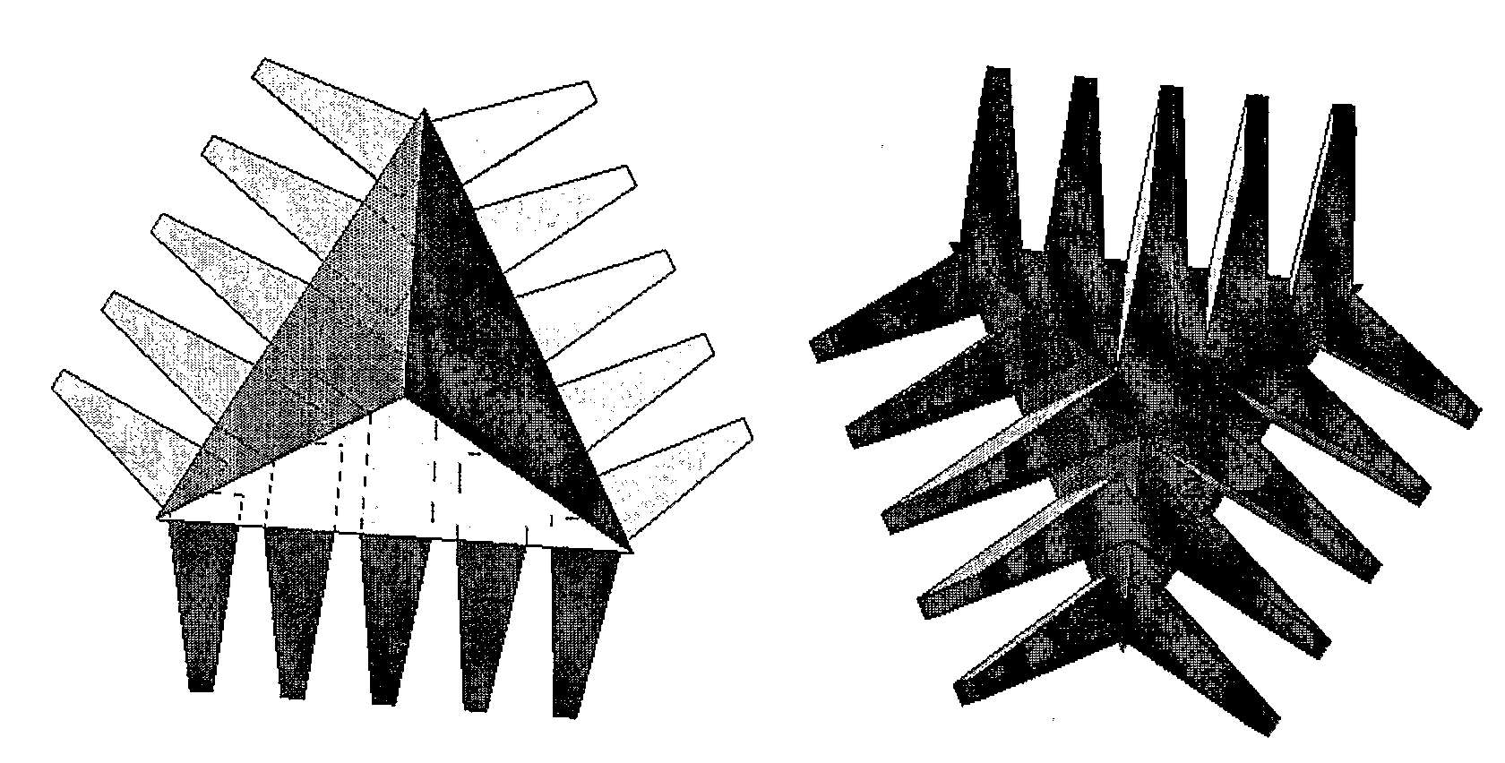
[0027]A cube corner consists of 3 mutually perpendicular reflecting planes in a pyramidal configuration. The point at which all three planes intersect is known as the apex of the cube-corner. In retro-reflecting, any incident ray strikes each of the surfaces once. As there are 3 planes, the order in which the planes are struck has 3 factorial combinations: 123, 132, 213, 231, 312, and, 321. These 6 combinations correspond to six distinct hexads (sub-apertures or non-contiguous wavefronts) on the front surface of the Cube Corner. Calculation of the polarization properties of the cube-corner requires calculation of the polarization properties of each of the six hexads. For each hexad, the calculation of the Mueller matrix is a product of four rotation matrices and three surface reflection matrices (J. Liu and R. M. A. Azzam, “Polarization properties of corner-cube retroreflectors: theory and experiment,” Appl. Opt. 36, 1553-1559 (1997), S. E. Segre and V. Zanza, “Mueller calculus of p...


PUM


Abstract

A cube corner retro-reflector that includes three mutually perpendicular reflecting planes arranged in a pyramidal configuration, wherein at least one of the reflecting planes has a non-isotropic surface causing a polarization state of a ray exiting the cube corner retro-reflector to be orthogonal or substantively orthogonal to a polarization state of a ray entering the cube corner retro-reflector for all linear polarization orientations.

Description

CROSS-REFERENCE TO RELATED APPLICATIONS[0001]This application is based upon and claims the benefit of priority to U.S. Provisional Application No. 60 / 732,089, filed Nov. 1, 2005, which is incorporated herein by reference.BACKGROUND OF THE INVENTION[0002]1. Field of the Invention[0003]The present invention relates generally to polarization-state-altering cube corners, and more particularly to methods and apparatuses for cube corners which rotate all linear polarizations by 90°, called linear polarization orthogonalization.[0004]2. Discussion of the Background[0005]A variety of applications, such as detection of objects passing a sensor (objects on a conveyor belt, cars at a toll booth, etc), and distance measurement, require an optical system as follows. The system is illuminated, by a lamp, laser or other optics, henceforth called the “source”. Some fraction of the irradiance from this source is transmitted through a beam splitter, and then over some path to a cube-corner retro-refl...

Claims


Application Information

Patent Timeline
IPC IPC(8): G02B27/28
CPCG02B27/286G02B5/122
Inventor CHIPMAN, RUSSELL A.CRABTREE, KARLTON
Owner THE ARIZONA BOARD OF REGENTS ON BEHALF OF THE UNIV OF ARIZONA
Why Eureka
Try Eureka