
Method of friction welding and friction welded part with at least two friction weld points

a technology of friction welding and friction welding part, which is applied in the direction of soldering apparatus, manufacturing tools,auxillary welding devices, etc., can solve the disadvantages of limiting oil flow, and achieve the effects of uniform expansion, good insertion characteristics, and long life cycl

Inactive Publication Date: 2009-09-03
GESENKSCHMIEDE SCHNEIDER GMBH
View PDF2 Cites 31 Cited by
  • Summary
  • Abstract
  • Description
  • Claims
  • Application Information

AI Technical Summary

Benefits of technology

[0014]In order to reduce the weld bead to a certain size in certain applications and to have to use only certain chipping or turning tools, the connected parts are assembled at least on one side by friction welding with no weld bead or with a very small weld bead. In this way, a weld bead can be completely eliminated within a predetermined width size.

Problems solved by technology

However, all of the weld beads limiting the oil flow are disadvantageous for the cooling.

Method used


Image

  • Method of friction welding and friction welded part with at least two friction weld points
  • Method of friction welding and friction welded part with at least two friction weld points
  • Method of friction welding and friction welded part with at least two friction weld points

Examples


second embodiment

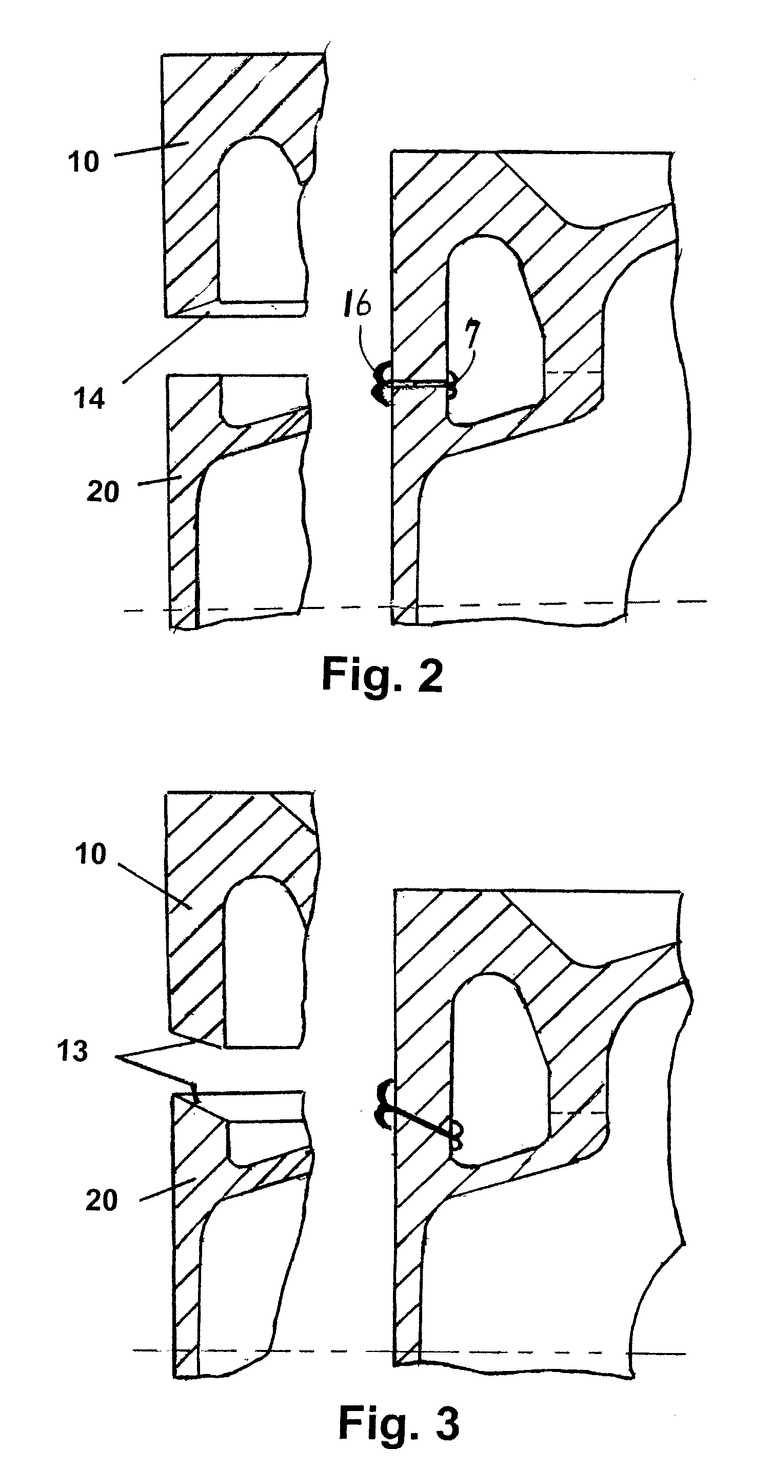
[0026]FIG. 3 shows a section of an external wall of a piston in accordance with a second embodiment before and after the friction welding process. In this case, the external wall of the piston is shaped so that both of the facing edge surfaces 13 to be welded are arranged in an inwardly downward angle so that the material accumulation is formed on the external area of the piston.

third embodiment

[0027]FIG. 4 shows a section of an external wall of a piston before and after the friction welding process. In this case, there are chamfers that create a recess in the area of the oil duct inside the piston walls, and in which the material of the weld bead can be accumulated after without limiting the internal width of the oil duct.

fourth embodiment

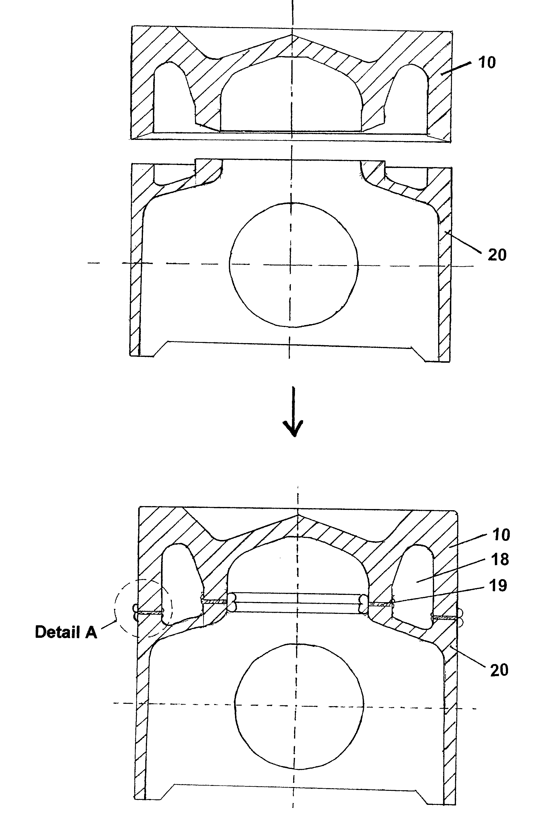
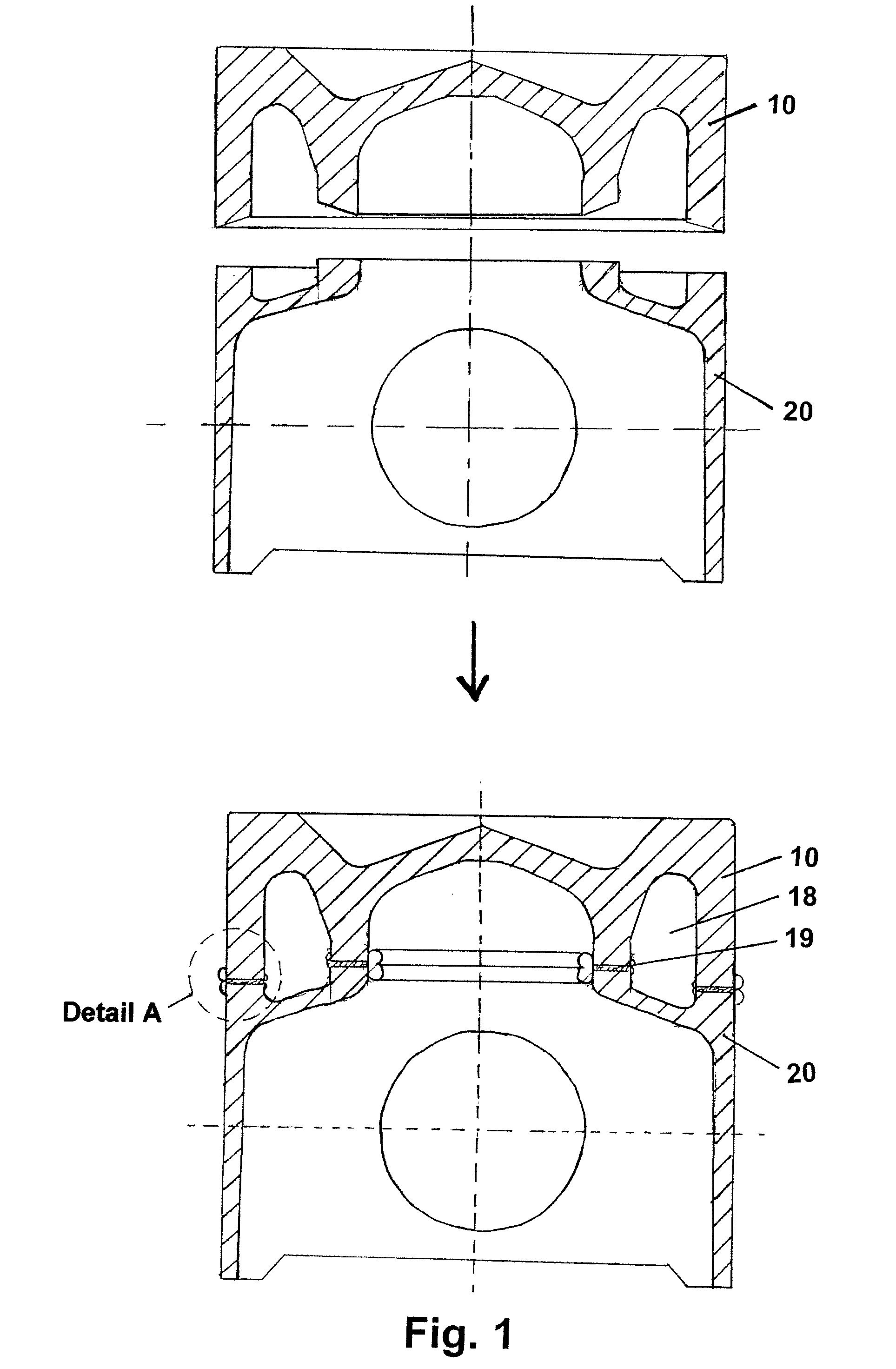
[0028]FIG. 5 shows a section of the walls of the top and lower parts 10, 20 of the piston. Here, the facing edge surfaces have nearly matched inter-fitting profiles, the inner sides of which remain out of contact, as shown, both before and after the friction welding process, so that there is substantially less material accumulated in the area of the oil duct.

[0029]FIG. 6 shows a similar concept to that of the FIG. 5 embodiment, the profiles being rounded instead of stepped. Here again, the inner sides of the inter-fitting profiles of the external wall of the piston parts 10, 20 remain out of contact, as shown, both before and after the friction welding process.

[0030]FIG. 7, 8 and 9 show sections of other embodiments of top and lower parts 10, 20 of a piston with inter-fitting profiles in which the inner sides of the inter-fitting profiles 13a of the external wall of the piston parts 10, 20 remain out of contact, as shown, both before and after the friction welding process and which ...


PUM

PropertyMeasurementUnit
Shapeaaaaaaaaaa
Areaaaaaaaaaaa
Strengthaaaaaaaaaa

Abstract

A method of friction welding a first part to a second part of a component having a hollow space in which the internal connection surface of the first part to be welded is reciprocally arranged with an internal connection surface of the second part to be friction welded, so that they form a unsymmetrical contact area, so that the resulting weld of the first and the second parts produces a weld bead that is located predominantly outside of the hollow space. The unsymmetrical contact area can be formed by a chamfer, angled edge surfaces that produce, for example, a wedge-shaped space, or partially matched, inter-fitting surfaces that remain out of contact at sides facing the hollow space.

Description

BACKGROUND OF THE INVENTION[0001]1. Field of Invention[0002]The present invention relates to a method for welding a first part with a second part by friction welding, wherein a hollow space in the component containing preferably small welding points is produced. The invention is also directed to a friction welded part produced according to the method of the present invention.[0003]2. Description of Related Art[0004]Forming of a connection between two parts by friction welding is known. Especially it is known, for example, as described in International Patent Application Publication WO 2006 / 034862 A1, in the case of a cooling duct piston, to connect the piston top with a piston shaft by friction welding. Also, from German Patent Application DE 10 2006 021 044 A1, it is known how to form the smallest weld beads as possible.[0005]In certain applications, however, not only is produced a friction weld connection, but more than one connection, wherein it is very important that the interna...

Claims


Application Information

Patent Timeline
IPC IPC(8): B32B15/01B23K20/12
CPCB23K20/129B23K33/006B23K33/008B23K37/06Y10T428/12764F02F3/22F02F2003/0061Y10T428/12493Y10T428/12965B23K2201/003B23K2101/003
Inventor KOLBE, PETERSCHMITZ, ERNST-PETER
Owner GESENKSCHMIEDE SCHNEIDER GMBH
Features
  • Generate Ideas
  • Intellectual Property
  • Life Sciences
  • Materials
  • Tech Scout
  • Unparalleled Data Quality
  • Higher Quality Content
  • 60% Fewer Hallucinations
Learn More