Anti-icing / de-icing system and method and aircraft structure incorporating this system

a technology of anti-icing and de-icing, applied in the direction of material analysis using sonic/ultrasonic/infrasonic waves, sound producing devices, vehicle maintenance, etc., can solve the problem of not optimizing the energy consumption which is required, and achieve the effect of maximizing vibratory energy and reducing energy consumption

Active Publication Date: 2009-09-10
HUTCHINSON SA
View PDF8 Cites 41 Cited by
  • Summary
  • Abstract
  • Description
  • Claims
  • Application Information

AI Technical Summary

Benefits of technology

[0027]In other words, each of the meshes of the or each matrix is protected from ice one after the other, by synchronously sending via the associated group of transducers traveling waves of lower amplitude but with a wavelength and phase that are recalculated at each instant to provoke a maximum of energy on the mesh (i, j) at the instance t then on the mesh (i+1, j+1) at the instant t+1, and so on. This mode of operation is advantageously less

Problems solved by technology

A major drawback of the known deicing systems for these aircraft structures lies notably in the non-optimized energy consumption which is re

Method used


Image

  • Anti-icing / de-icing system and method and aircraft structure incorporating this system
  • Anti-icing / de-icing system and method and aircraft structure incorporating this system
  • Anti-icing / de-icing system and method and aircraft structure incorporating this system

Examples


Embodiment Construction

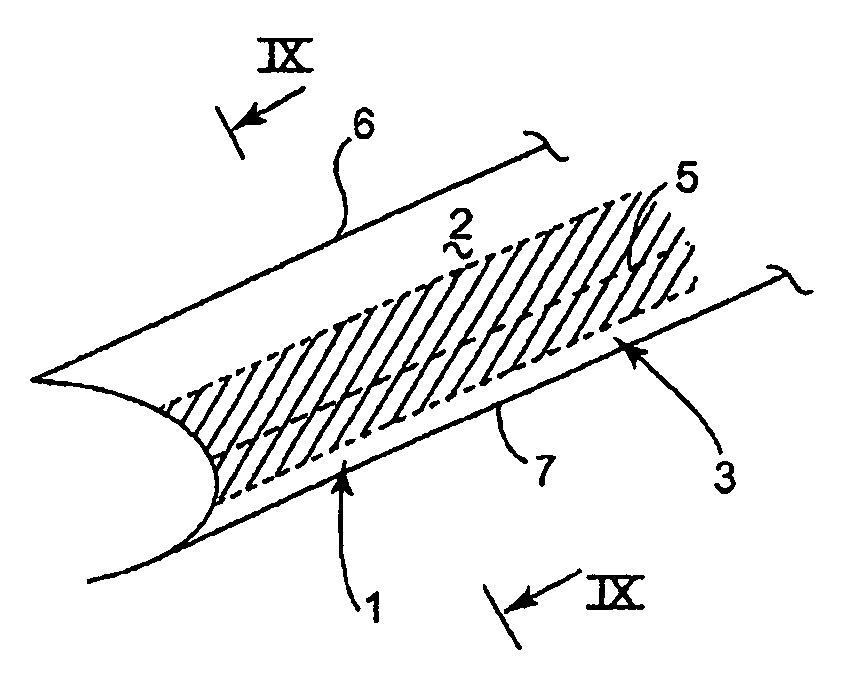
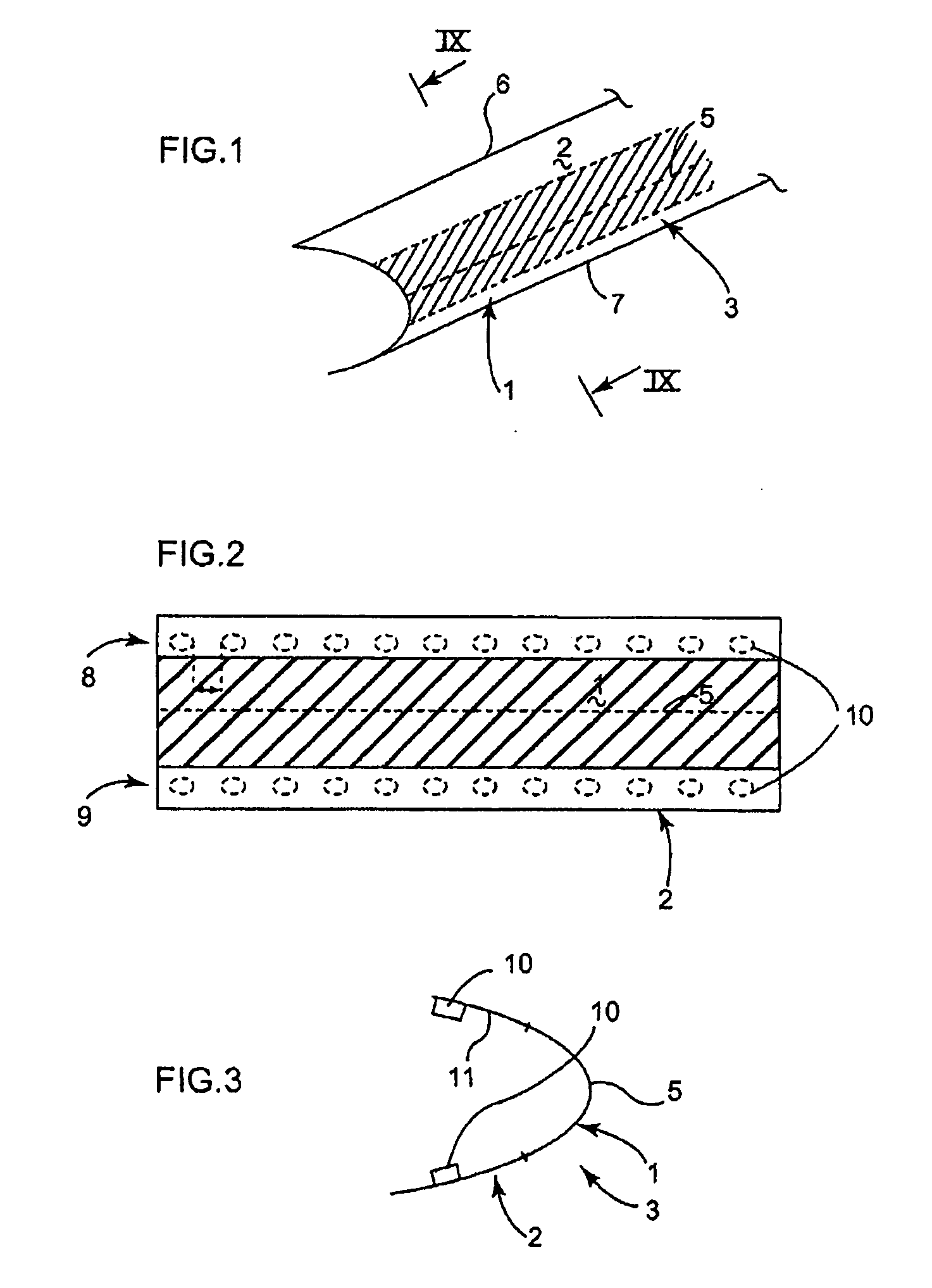
[0052]FIG. 1 shows a typical example of geometry of area 1 to be protected from icing or to be de-iced on an external surface 2 of an aircraft structure 3, such as an airplane wing or a helicopter blade, using the anti-icing / de-icing system 4 according to the invention (diagrammatically represented in FIG. 4). This area 1 allows as its longitudinal axis of symmetry, the leading edge line 5 of the wing or of the blade and extends on either side of this axis over the upper surface 6 and the lower surface 7 of the wing, for example.

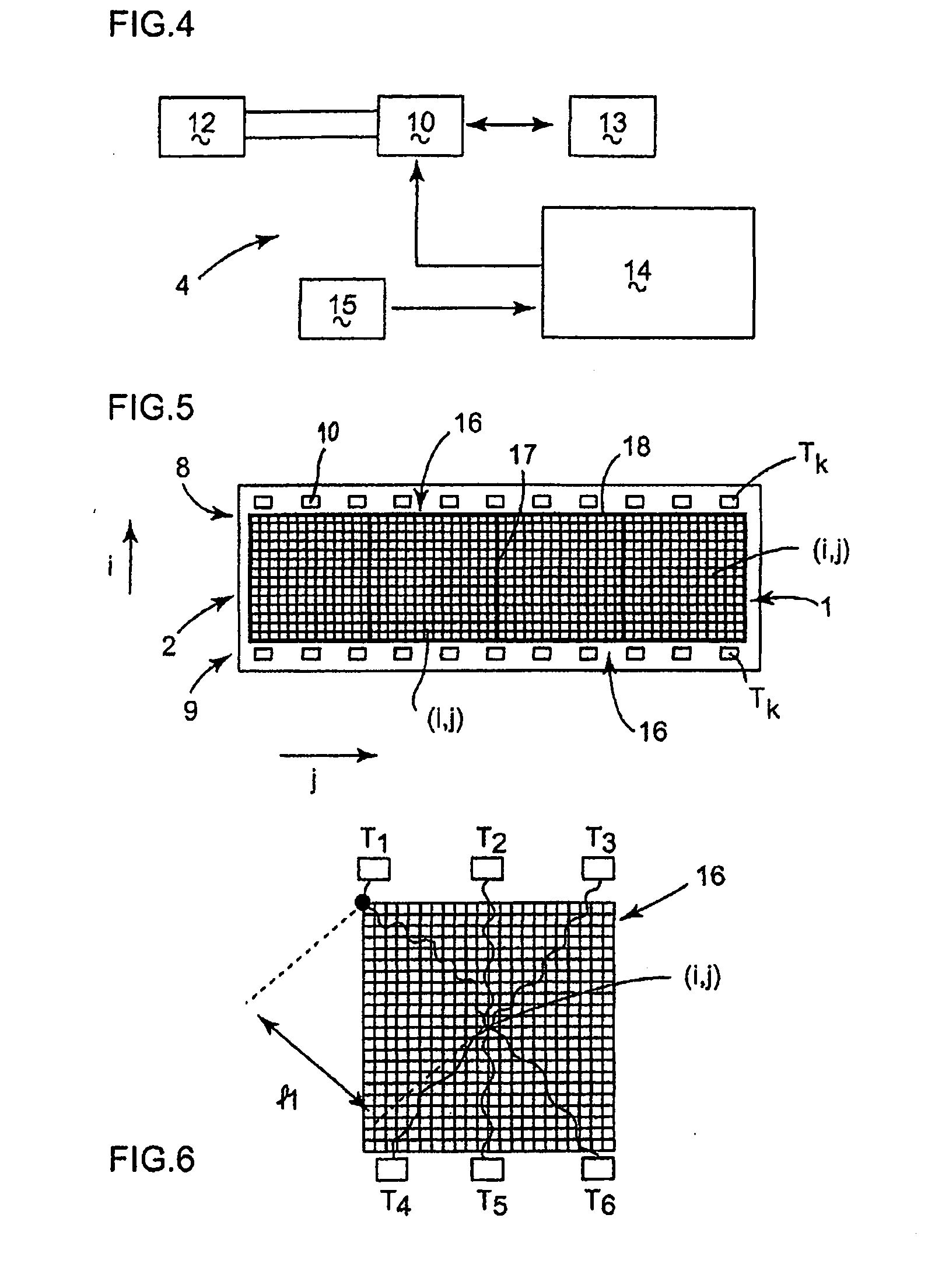
[0053]FIGS. 2 and 3 show the preferred arrangement according to the invention of two series 8 and 9 of reversible piezoelectric transducers 10 (i.e., transducers that can operate only in emitting mode, in anti-icing mode, or also in receiving mode, in de-icing mode) on either side of this area 1 and on the internal face 11 of the structure 3 opposite to its external surface 2 to be treated. Each transducer 10 is designed to exhibit minimal dimensions, with a...


PUM


Abstract

The present invention provides an anti-icing/de-icing system and method using ultrasound waves for an external surface of a structure likely to be iced, such as an aircraft wing or engine nacelle, and such a structure incorporating this system. The system comprises a plurality of piezoelectric transducers with which the structure is fitted, opposite this external surface, and this system is such that it comprises means of scanning at least one matrix of elementary meshes predefined in this surface in relation to an even arrangement of a group of these transducers, these scanning means being able to focus the waves emitted by all or some of the transducers of the or each group on these meshes one after the other, via signal summing means coupled to these scanning means and able to produce, for each mesh, a summation of the signals obtained from the transducers emitting these waves.

Description

CROSS REFERENCE TO RELATED APPLICATION[0001]This application claims priority to French Application No. 08 01202, filed Mar. 5, 2008.FIELD AND BACKGROUND OF THE INVENTION[0002]The present invention relates to an anti-icing / de-icing system using ultrasound waves for an external surface of a structure likely to be iced, such as an aircraft wing or engine nacelle, such a structure incorporating this system and an anti-icing / de-icing method implemented by this system.[0003]The use of ultrasound waves for de-icing airplane wings, helicopter blades or aircraft engine nacelles in particular is known. Document DE-A-10 2004 060 675 describes a device and a method using piezoelectric transducers arranged behind the leading edge of an airplane wing to handle the de-icing of the latter, with a working frequency chosen according to the rigidity of the structure of this wing.[0004]Also known from the document WO-A-2007 / 095935 is the use of a two-dimensional network of transducers incorporated insi...

Claims


Application Information

Patent Timeline
IPC IPC(8): B64D15/00
CPCB60S1/02G10K11/346G10K11/343B64D15/163B64D15/20G01N29/00B64D15/12G01K1/14
Inventor TENEBRE, PAULINESIX, MARC-FRANCOIS
Owner HUTCHINSON SA
Why Eureka
Try Eureka