Process for conversion of natural gas to liquid hydrocarbons and a plant for carrying out the process

a technology of liquid hydrocarbons and natural gas, which is applied in the direction of chemistry apparatus and processes, sustainable manufacturing/processing, metal processing, etc., to achieve energy-saving effects

Active Publication Date: 2017-06-20
VITESCO TECH USA LLC +1
View PDF3 Cites 0 Cited by
  • Summary
  • Abstract
  • Description
  • Claims
  • Application Information

AI Technical Summary

Benefits of technology

[0005]It is an object of the present invention to provide a process and plant which is more energy efficient and more inexpensive than prior art processes, particularly for small GTL plants.
[0008]We have found that by providing a cryogenic air separation unit in combination with autothermal reforming or catalytic partial oxidation, pressure swing adsorption of raw synthesis gas from the ATR as well as Fischer-Tropsch tail gas recycle to the hydrocarbon feed or to the ATR, significant and unexpected advantages are obtained.
[0022]In another embodiment in connection with any of the above or below embodiments, step (a) further comprises using Vacuum Pressure Swing Adsorption (VPSA). Accordingly, the oxygen with purity of at least 80% vol. is provided by combining cryogenic ASU and VPSA. By combining these units it is possible to reduce the capital costs associated with the provision of the oxygen. VPSA units are also simpler than ASU units and also smaller in size.
[0023]In yet another embodiment in connection with any of the above or below embodiments, the hydrogen-rich stream of step (d) is used in hydroprocessing units downstream, such as hydrocracking or hydrotreating units in the upgrading section of the Fischer-Tropsch synthesis, or in the desulphurization step, as described above, or in both. The provision of the hydrogen-rich stream of step (d) in the desulphurization step, e.g. prior to step (b) enables reducing the size of the desulphurization section due to the higher purity of the hydrogen. By way of comparison, a hydrogen stream from H2-membranes will include CO2 and H2O moisture which will impact the H2S absorption and result in undesired H2S slippage from the desulphurization step to the pre-reformer(s) and / or autothermal reformer. Contrary to the prior art, particularly if a H2-membrane were used, the hydrogen removed in the PSA has already an elevated pressure, e.g. 20 atm, for downstream processes such us units within the upgrading section of the Fischer-Trospch section, for instance hydroprocessing units, more particularly hydrocracking units. A booster compressor is still needed, but it is much less energy intensive and thereby much less expensive than compressing from atmospheric pressure. In addition, since the H2 purity from the PSA is higher than a H2-membrane, i.e. >99.9% instead of 92-98%, the amount of hydrogen required is reduced. This enables additional reduction of highly expensive compression requirements and concomitantly better energy efficiency in the process is achieved. For example, hydrogen that comes from the PSA is at high pressure, but not the required pressure (i.e. it is 20 bar vs a few bars). A compressor to recycle back to the desulphurization step upstream may be required as so is a compressor to the hydrocracking section downstream. Yet, these compressors are significantly smaller compared to a situation where a H2-membrane is utilized.
[0026]In yet another embodiment in connection with any of the above or below embodiments, steam is added to the oxygen of step (a). Hence, the oxygen from the cryogenic ASU optionally including VPSA, is mixed with steam prior to entering the ATR or CPO. The steam serves to dilute the oxygen to the required levels in the ATR thereby providing safety and further enabling use of inexpensive construction materials.

Problems solved by technology

This development is at least partly driven by poor pipeline accessibility to the remote places where such smaller natural gas reserves (fields) are located.

Method used


Image

  • Process for conversion of natural gas to liquid hydrocarbons and a plant for carrying out the process
  • Process for conversion of natural gas to liquid hydrocarbons and a plant for carrying out the process

Examples


Embodiment Construction

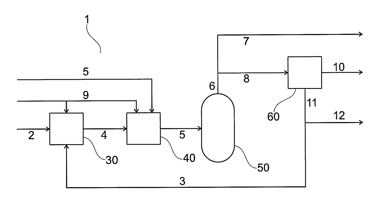
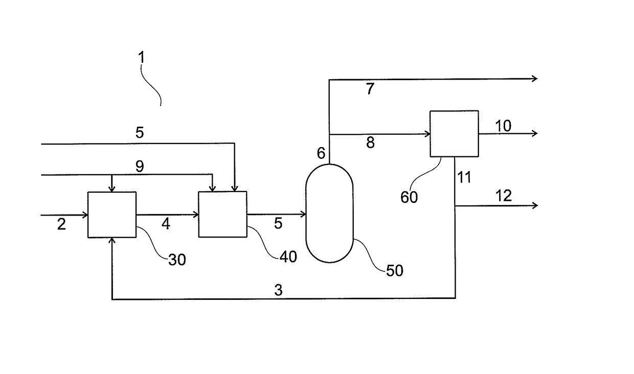
[0048]In the FIGURE, a schematic process and plant 1 for producing about 3000 BPD of liquid hydrocarbon product is shown. A feed hydrocarbon stream such as natural gas 2 is passed through a desulfurization unit 30 suitably arranged as a hydrogenator followed by an absorption unit (not shown). To the natural gas 2 or to the desulfurization unit 30, more specifically to the hydrogenator therein, a hydrogen-rich stream 3 from the PSA-unit downstream is added. The desulfurized stream 4 is then mixed with steam and pre-reformed in one or more pre-reformers (not shown) before entering an autothermal reformer (ATR) 40 under the addition of oxygen 5. A raw synthesis gas 6 is withdrawn from the ATR, cooled in heat exchangers and air cooler (not shown) before passing to a water removal unit 50 such as a process condensate separator. A large portion of water is removed from this unit and the raw synthesis gas 6a, now dewatered, is split into a first raw synthesis gas 7 which represents the maj...


PUM

PropertyMeasurementUnit
molar ratioaaaaaaaaaa
temperaturesaaaaaaaaaa

Abstract

Process and plant for conversion of a feed hydrocarbon stream to liquid hydrocarbon products in a small scale GTL plant, comprising the use of a cryogenic air separation unit (ASU), optionally together with vacuum pressure swing adsorption (VPSA), an autothermal reformer (ATR) or catalytic partial oxidation (CPO), and pressure swing adsorption (PSA) unit to produce a synthesis gas for downstream Fischer-Tropsch (FT) synthesis for production of liquid hydrocarbons.

Description

BACKGROUND OF THE INVENTION[0001]The present invention relates to a process for conversion of a feed hydrocarbon stream such as natural gas to liquid hydrocarbon products. More specifically, the invention relates to a process comprising the use of a cryogenic air separation unit (ASU), optionally together with vacuum pressure swing adsorption (VPSA), to provide oxygen with purity of at least 80% vol. The feed hydrocarbon stream is combined with steam, optionally with subsequent pre-reforming, and passed with the oxygen through an autothermal reformer (ATR) or catalytic partial oxidation (CPO) to produce a raw synthesis gas, of which a portion is passed through a pressure swing adsorption (PSA). The raw synthesis gas is used in downstream Fischer-Tropsch synthesis for production of liquid hydrocarbons, including production of a Fischer-Tropsch tail gas stream which is recycled to e.g. the feed hydrocarbon stream prior to or after addition of steam, or to the ATR or CPO. The invention...

Claims


Application Information

Patent Timeline
Patent Type & Authority Patents(United States)
IPC IPC(8): C01B3/38C10G2/00
CPCC10G2/30C01B3/382C01B2203/0244C01B2203/062C01B2203/0261C01B2203/043C01B2203/142C01B2203/148C21B13/0073C21B2100/24C21B2100/26Y02P10/134Y02P10/143
Inventor CHRISTENSEN, THOMAS SANDAHL
Owner VITESCO TECH USA LLC
Why Eureka
Try Eureka