
Gas cylinder monitoring system

Active Publication Date: 2021-04-20
LINDE AG
View PDF31 Cites 0 Cited by
  • Summary
  • Abstract
  • Description
  • Claims
  • Application Information

AI Technical Summary

Benefits of technology

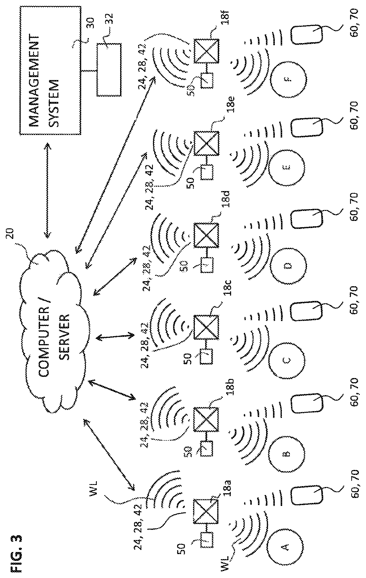
The present invention provides a monitoring system for gas cylinders that consumes less energy than existing systems. This is achieved by broadcasting data in a discrete advertisement package at a controlled time and / or time interval, reducing the amount of data sent and energy consumed. The system uses Bluetooth wireless technology to transmit data between devices, with the first monitoring system continuously sending data and the second monitoring system receiving it as a discrete package, without the need for pairing or connecting. This results in less energy being consumed compared to devices that connect or pair with each other to enable data transmission. The first monitoring system analyzes data to determine the time and / or time interval at which the advertisement package is broadcast, and can control the output of the gas cylinder based on the data analysis, such as disabling an alarm or controlling gas flow. The use of Bluetooth and low energy Bluetooth (BLE) further reduces energy consumption.

Problems solved by technology

The tracking of cylinders and the management of gas supply whilst at locations within the process is problematic as it is sometimes difficult to monitor the location of the cylinders and the data associated with the cylinder, for example, and importantly, the time remaining before the cylinder runs out of gas.
It is also known to supply cylinder systems with gauges displaying the pressure of gas remaining, but human intervention is required in order to retrieve the information and some users may find it difficult to interpret the information supplied and may make incorrect determinations of important data such as the total time of gas supply remaining.
Still further, it is very difficult to locate cylinder systems which may be past their use-by date or which may be obsolete or inappropriate for a particular location.
One problem with battery powered monitoring systems is the energy intensive nature of the wireless transmissions which result in the batteries draining quickly and can eventually lead to inoperation of the monitoring system and therefore not knowing the status and / or the location of the gas cylinders.

Method used


Image

  • Gas cylinder monitoring system
  • Gas cylinder monitoring system
  • Gas cylinder monitoring system

Examples


Embodiment Construction

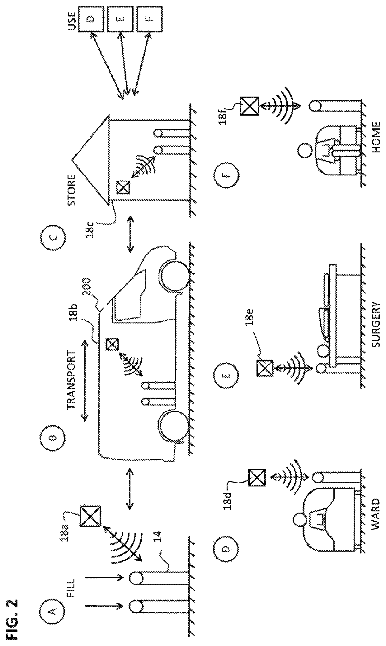
[0026]Referring now to the drawings in general but particularly to FIG. 1, it will be appreciated that a gas cylinder system 14 may be located in any one of a number of locations during its lifecycle and that it is often difficult simply to locate a cylinder that is known to be in the supply chain. The typical supply chain includes a number of locations including but not limited to a filling station (A), a transportation vehicle (B), a storage facility (C) and any one of a number of use locations such as those shown at D to F. Such use locations may include a hospital ward (D), surgery, (E) or home (F) as shown in FIG. 2.

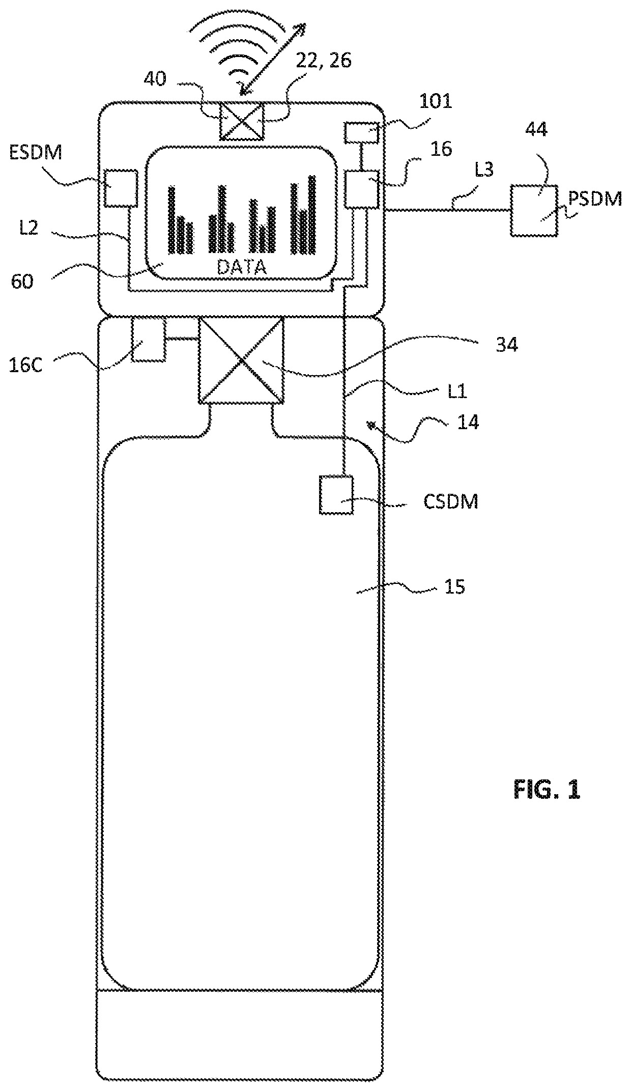
[0027]The gas cylinder system 14 comprises a gas cylinder 15 and a first monitoring system 16 for monitoring cylinder specific data associated with the gas cylinder 15. The first monitoring system 16 is powered by a battery (not shown) as it is not practical to connect to a mains power supply as the gas cylinder system 14 is frequently moved from location to locatio...


PUM


Abstract

A gas cylinder monitoring system is disclosed having a gas cylinder for receiving and distributing gas contained therein, a first monitoring system associated with the gas cylinder operable to monitor data associated with the gas cylinder and having a transmitter operable to broadcast the data at a controlled time and / or time interval in a discrete advertisement package, and a second monitoring system associated with one or more locations in which the first monitoring system may reside and having a receiver operable in a first mode to receive the advertisement package broadcast from the first monitoring system when the second monitoring system is within range of the first monitoring system.

Description

CROSS-REFERENCE TO RELATED APPLICATIONS[0001]This application claims priority under 35 USC § 119 to International Patent Application No. PCT / EP2017 / 060949, filed on May 8, 2017 which claims priority from Great Britain Patent Application GB 16 084 87.3, filed on May 13, 2016.BACKGROUND OF THE INVENTION[0002]The present invention relates to a gas cylinder monitoring system, in particular to a gas cylinder monitoring system using gas cylinders for supplying clinical gasses such as, for example, oxygen, argon, nitrous oxide, xenon, nitric oxide, helium and mixtures thereof to patients, and for supplying industrial gases such as oxygen, nitrogen and argon and mixtures thereof.[0003]It is known to supply gas cylinders into a process including filling, transporting, storing and using before having the cylinders returned to the supplier for re-filling and then re-circulation within the process. The tracking of cylinders and the management of gas supply whilst at locations within the process...

Claims


Application Information

Patent Timeline
IPC IPC(8): G16H40/67G06Q10/08A61M16/00F17C13/02
CPCG16H40/67A61M16/0051F17C13/02G06Q10/08G06Q10/0832A61M2205/18A61M2205/3584F17C2250/032F17C2250/034F17C2250/036F17C2270/02F17C2270/0745G06Q10/087F17C2205/058
Inventor THIND, MANDIPPEREZ DE ALEJO FORTUN, RIGOBERTOJACOBSEN, BRIAN
Owner LINDE AG
Learn More