Material cutter clamping collet

a technology of material cutter and clamping collet, which is applied in the direction of shaping cutter, tube shearing machine, manufacturing tools, etc., can solve the problems of requiring significant machining, affecting the quality of material cutter, and the finger typically not fully retracting, so as to increase the replacement interval of the collet, the effect of reducing the drag

Inactive Publication Date: 2009-09-10
BRASSCRAFT MFG CO
View PDF44 Cites 8 Cited by
  • Summary
  • Abstract
  • Description
  • Claims
  • Application Information

AI Technical Summary

Benefits of technology

[0006]Accordingly, the disclosed collet is forced out of engagement by the biasing member, thus decreasing drag and increasing collet replacement intervals. Replaceable inserts can also be secured to each finger facing the opening, which enables only the inserts to be replaced as they become worn instead of replacing the complex collet.

Problems solved by technology

The structure of the collet is rather complex, requiring significant machining.
However, the fingers typically do not fully retract.
This results in the fingers creating drag on the material, which wears the collet out after several days of operation.
The manufacturing operation must be shut down each time the collet is replaced, thus increasing part cost and reducing production output.

Method used


Image

  • Material cutter clamping collet
  • Material cutter clamping collet
  • Material cutter clamping collet

Examples


Embodiment Construction

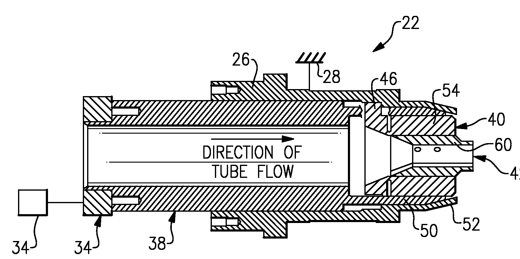
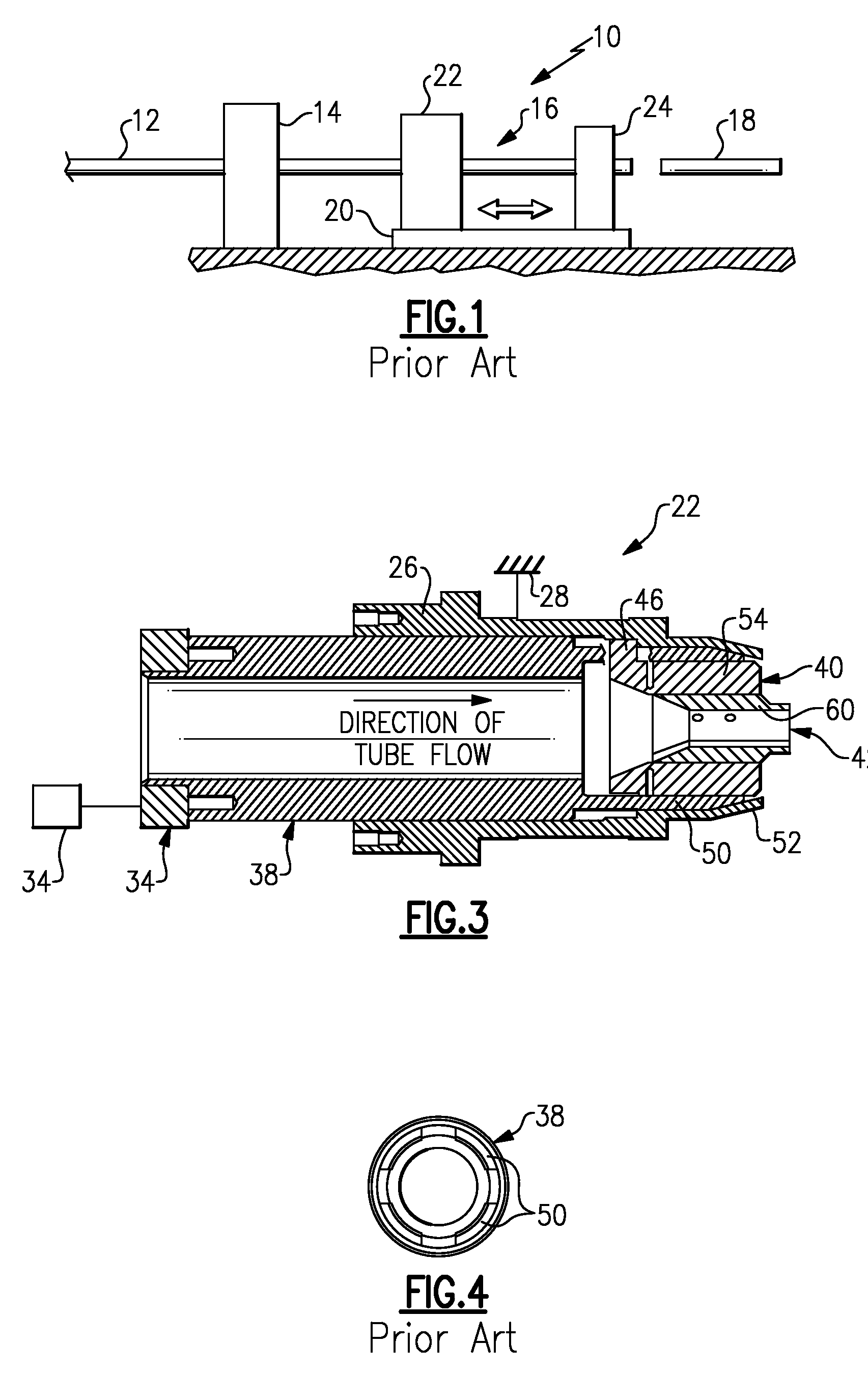
[0014]A material cutter 10 is schematically shown in FIG. 1. The material cutter 10 includes a feeder 14 that continuously feeds material 12, such as tubing. A cutter assembly 16 receives the material 12 and cuts it to a desired length 18. The cutter assembly 16 is mounted on a shuttle 20 that moves relative to the feeder 14 to enable continuous feeding of the material 12. The cutter assembly 16 includes a clamping assembly 22 and a cutter 24. The clamping assembly 22 holds the material 12 while the cutter 24 cuts the material 12 to a desired length 18.

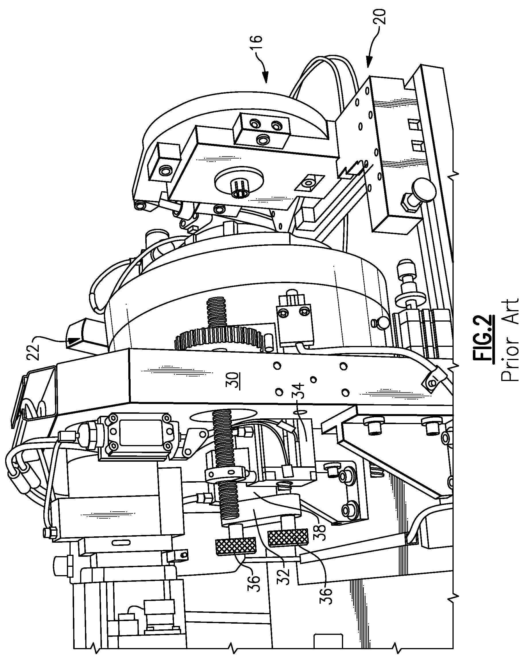
[0015]Referring to FIGS. 2 and 3, the clamping assembly 22 includes a spindle 26 supported by a housing 28. The housing 28 is secured to the shuttle 20 by support 30. The spindle 26 includes a tapered collar 52, best shown in FIG. 3. A clamping sleeve 38 is slidably received within the spindle 26 and is movable along an axis A. The material 12 is fed into the clamping sleeve 38 along the axis A. Returning to FIG. 2, a bracket 32 is se...


PUM

PropertyMeasurementUnit
inner diameteraaaaaaaaaa
flexibleaaaaaaaaaa
lengthaaaaaaaaaa

Abstract

A clamping assembly is disclosed that includes a tapered collar extending radially inward towards an axis. A clamping sleeve is movable along the axis relative to the tapered collar. The clamping sleeve includes flexible arms. An actuator is coupled to the clamping sleeve and is configured to move the clamping sleeve along the axis between extended and retracted positions. A collet is supported relative to the sleeve. The collet includes a body having an axially extending opening configured to receive the material and circumferential fingers arranged about the opening. The clamping sleeve forces the fingers radially inward with the clamping sleeve in the extended position to clamp and hold the material. The biasing member urges the fingers radially outward with the clamping sleeve in the retracted position. Replaceable inserts can also be secured to each finger facing the opening.

Description

BACKGROUND[0001]This disclosure relates to a clamping assembly used with a material feeder. More particularly, the disclosure relates to a collet used in the clamping assembly.[0002]A manufacturing operation includes a material feeder that provides material, such as tubing, to a cutter assembly, which cuts the material to a desired length. The cutter assembly includes a clamping assembly that clamps the material while it is cut to length.[0003]In one example arrangement, the clamping assembly includes a plastic collet having multiple circumferentially arranged fingers. The structure of the collet is rather complex, requiring significant machining. A clamping sleeve cooperates with the collet when in an extended position to force the fingers radially inward to clamp the material. After the material is cut, the clamping sleeve is retracted to release the fingers from clamping engagement with the material. However, the fingers typically do not fully retract. This results in the fingers...

Claims


Application Information

Patent Timeline
Patent Type & Authority Applications(United States)
IPC IPC(8): B23Q3/12B23P15/36
CPCB23D21/00B23D33/02Y10T407/2276B26D2007/013Y10T279/17461B26D7/02Y10T279/17119Y10T279/17341Y10T279/17521Y10T279/17427B23B31/2072B26D7/01
Inventor HOMRICH, PAUL ROBERT
Owner BRASSCRAFT MFG CO
Why Eureka
Try Eureka