Led lamp system and method of making same

a technology of led lamps and lamps, which is applied in the direction of lighting and heating apparatus, coupling device connections, instruments, etc., can solve the problems of affecting the reliability of lamps, and affecting the downsizing of lamps

Active Publication Date: 2009-09-10
TOYODA GOSEI CO LTD
View PDF7 Cites 19 Cited by
  • Summary
  • Abstract
  • Description
  • Claims
  • Application Information

AI Technical Summary

Benefits of technology

[0010]It is an object of the invention to provide an LED lamp system that can prevent a malfunction due to external force when attached to an external connector while being further downsized and providing a circuit portion on PCB.
[0034]wherein the branch part is sandwiched and held by a holding portion formed on an inside wall of the case for preventing a failure caused by external force applied when connecting the connection terminal to the external connector.
[0035]The above LED lamp system is composed such that the connection terminal soldered to the printed circuit board for connecting to the external connector is provided with the branch part, and the case for enclosing the printed circuit board is provided with the holding portion for holding the branch part so as to prevent deformation of the connection terminal by the branch part and the holding portion. Thus, deformation of the connection terminal can be prevented when external force is excessively applied to the connection terminal, and the external force can be prevented from concentrating on the solder joint portion, i.e., the soldering part so that no crack or electrical connection failure can be caused therein.
[0038]Thereby, the external force applied to the soldering part can be further reduced, and the branch part can be prevented from being detached from the holding portion.
[0040]Thereby, external force applied to the printed circuit board can be also reduced to prevent a malfunction in a circuit or a circuit protection element mounted on the printed circuit board.

Problems solved by technology

Thereby, electrical or electronic parts etc. mounted on the metal board may cause a malfunction.
In the LED lamp systems of JP-A-2002-036950 and 2001-243829, although the above problem may be solved since connection terminal is soldered to the PCB, the external force when attached thereto is directly applied to a soldering part and a crack or electrical connection failure may be thereby caused to lower the reliability.
Thus, when the number of the soldering parts increases, the downsizing of the lamp system will be impaired since a space is further needed to secure the distance and to dispose the soldering parts.
Especially in case of an in-vehicle light source, this problem will be more serious since the light source needs to be placed in a very limited space in the vehicle.

Method used


Image

  • Led lamp system and method of making same
  • Led lamp system and method of making same
  • Led lamp system and method of making same

Examples


first embodiment

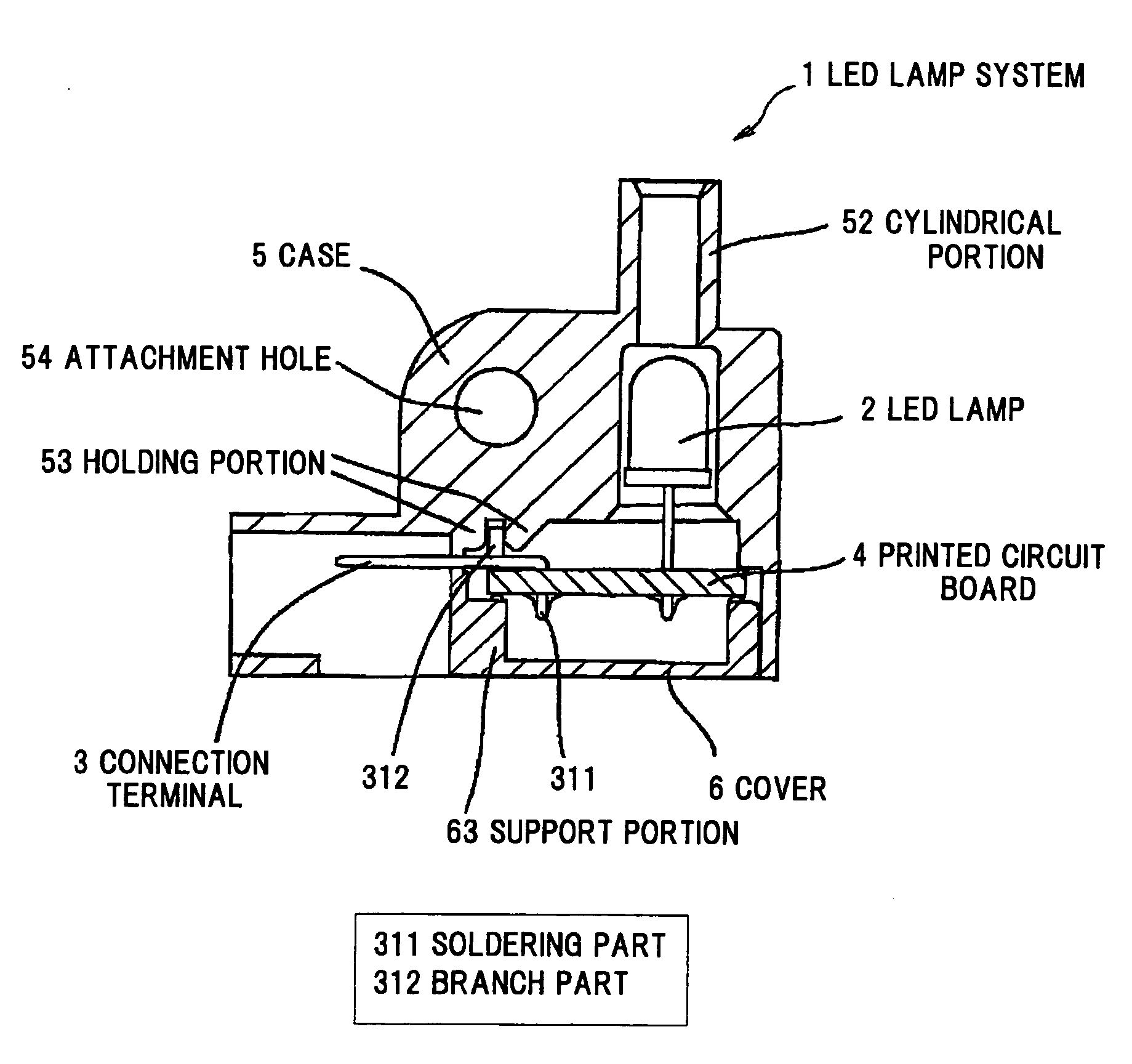
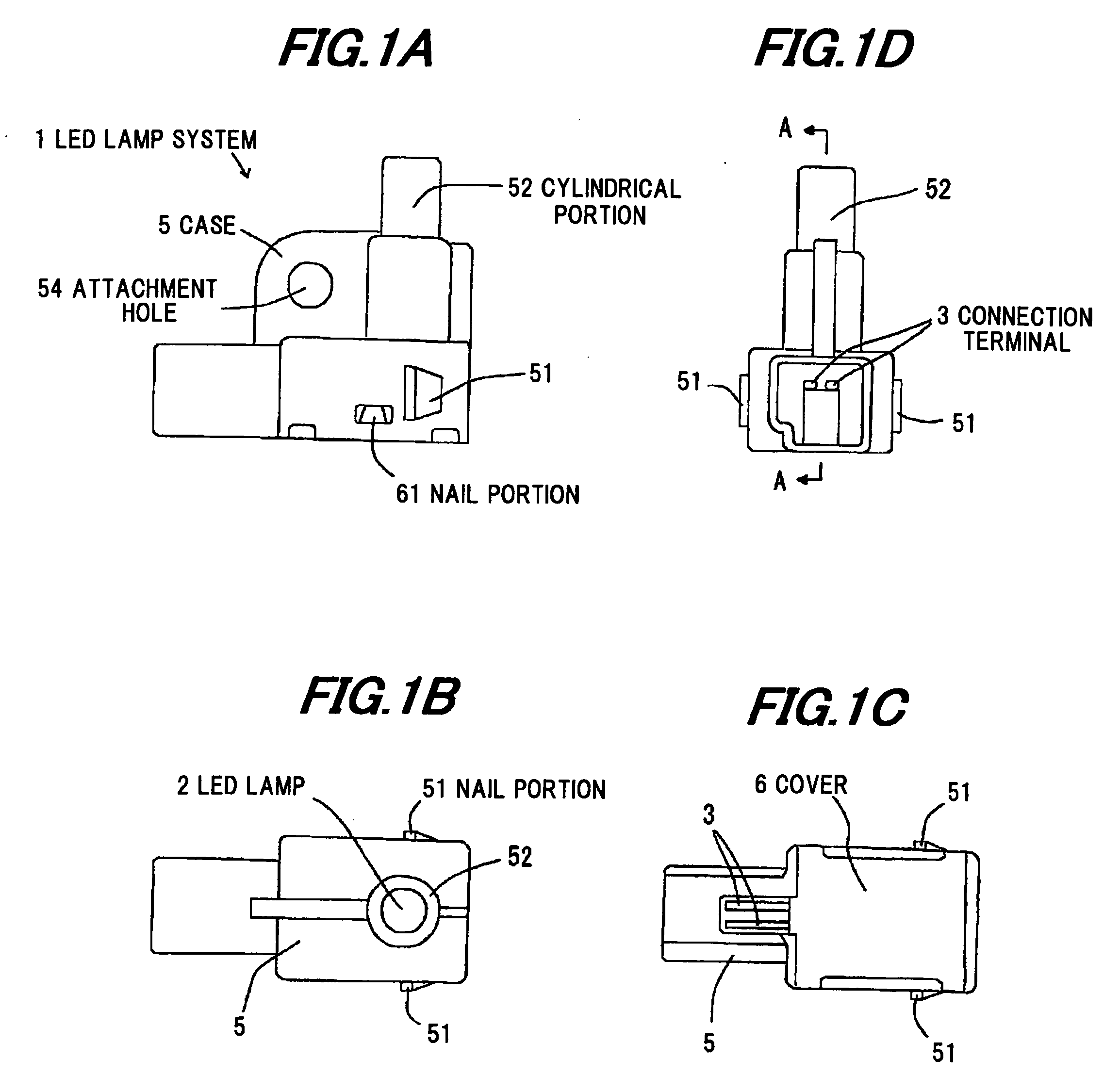
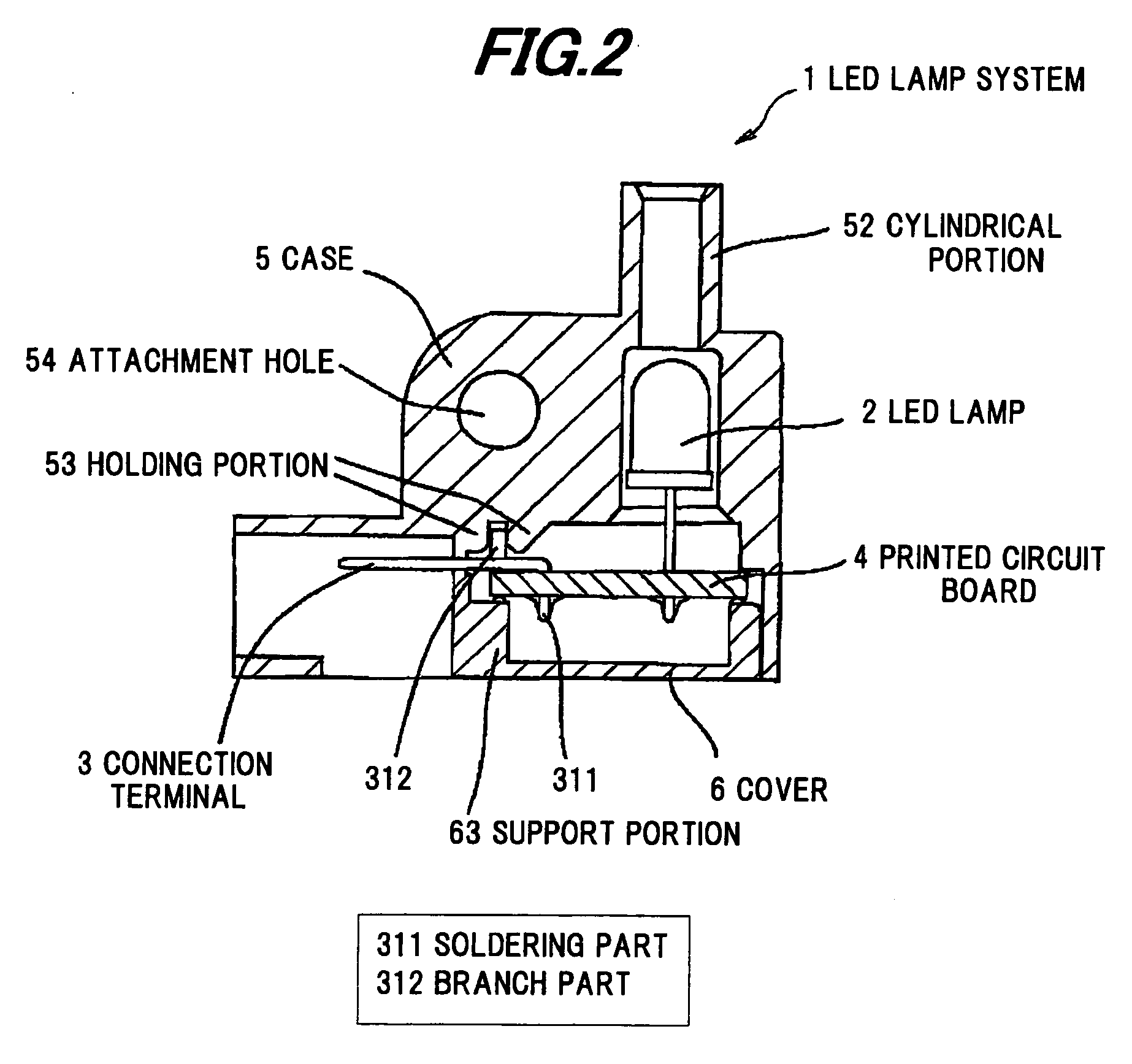
[0055]The first preferred embodiments of the invention will be explained below referring to the drawings. FIGS. 1A to 1D each show the appearance of an LED lamp system 1 of the first embodiment, where FIG. 1A, FIG. 1B, FIG. 1C and FIG. 1D are a left side view, a top view, a bottom view, and a front view, respectively, of the LED lamp system 1. FIG. 2 is a cross sectional view showing the LED lamp system 1. FIG. 3 is a perspective view showing lead members 31, 32 used as a connection terminal 3 of the LED lamp system 1.

[0056]A bullet-type LED lamp 2 is soldered to a printed circuit board 4. The lead members 31, 32 as the connection terminal 3 are folded by nearly 90 degrees at one end thereof to provide soldering parts 311, 321. The soldering parts 311, 321 are inserted penetrating through corresponding insertion holes in the printed circuit board 4 and soldered to the back surface of the printed circuit board 4 to secure the lead members 31, 32 to the printed circuit board 4. A circ...

second embodiment

[0067]As shown in FIGS. 4 and 5, an LED lamp system 11 in the second preferred embodiment of the invention can be, according to the versatility, made in which the case 5 is modified in formation. In FIGS. 4 and 5, like components are indicated by the same numerals as used in the first embodiment.

[0068]As shown in FIGS. 4 and 5, the second embodiment is different from the first embodiment in that the nail portion 51 is removed and the attachment hole 54 is formed cylindrical. The cylindrical attachment hole 54 allows more firm attachment of the system than the first embodiment such that the system can be fixed to the external member by using a fixing member such as a screw and a rod in association with the attachment hole 54. Optionally, where the fixing member is a screw, the inside wall of the attachment hole 54 may be threaded to receive the screw. Thereby, the system can be securely positioned by being rotated around the fixing member as a rotational axis. Meanwhile, in case of f...

third embodiment

[0069]FIGS. 6 to 8 show an LED lamp system 101 in the third preferred embodiment of the invention.FIG. 6 is a cross sectional view showing the LED lamp system 101, FIG. 7 is a perspective view showing lead members 131, 132 as a connection terminal 103, and FIG. 8 is a top view showing the connection terminal 103 and a printed circuit board 104.

[0070]As shown in FIG. 6, the LED lamp system 101 is composed of a printed circuit board 104 on which a bullet-type LED lamp 102 is mounted, the connection terminal 103 electrically connected to the printed circuit board 104, a case 5 to which the printed circuit board 104 is fixed, and a cover 106 in which the LED lamp 102 and the printed circuit board 104 are enclosed in association with the case 105. The LED lamp 102 is mounted on the printed circuit board 104 by soldering. The LED lamp 102 may be the SMD type or the SV type other than the bullet-type.

[0071]As shown in FIG. 7, the connection terminal 103 is composed of a pair of lead member...


PUM


Abstract

An LED lamp system includes a light emitting diode (LED) lamp, a printed circuit board on which the LED lamp is mounted, a connection terminal including a soldering part inserted and soldered to the printed circuit board, a body part extending parallel to the printed circuit board, and a branch part extending from the body part in a predetermined direction, a case to which the printed circuit board is fixed, the case including a holding portion for holding the branch part of the connection terminal, and a cover for enclosing the LED lamp and the printed circuit board in association with the case.

Description

[0001]The present application is based on Japanese patent application Nos. 2008-056663 and 2008-332188 filed Mar. 6, 2008 and Dec. 26, 2008, respectively, the entire contents of which are incorporated herein by reference.BACKGROUND OF THE INVENTION[0002]1. Field of the Invention[0003]This invention relates to an LED lamp system and a method of making the LED lamp system.[0004]2. Description of the Related Art[0005]Conventional LED lamps include a bullet type or SMD (surface mount device). For example, an LED lamp system for a vehicle lamp is constructed such that leads of the LED lamp are soldered to a printed circuit board (PCB) and the PCB is then secured to a case portion, and installed at a given position of the vehicle. The PCB is wired to a lighting control device of the vehicle such that flashing of the LED and brightness or emission color of the lighted LED are controlled by a vehicle switch or a control circuit.[0006]JP-A-2002-036950 and 2001-243829 disclose LED lamp system...

Claims


Application Information

Patent Timeline
Patent Type & Authority Applications(United States)
IPC IPC(8): H01J5/50H01J9/24B60Q3/02H01L33/48H01R13/717
CPCF21K9/00Y10S362/80F21V23/06G02B6/428G02B6/4298B60Q3/51B60Q3/64
Inventor ICHIKAWA, TADAOKIUMEDA, YUKIHIKO
Owner TOYODA GOSEI CO LTD
Why Eureka
Try Eureka