
Touch panel, liquid crystal display apparatus, and method for manufacturing thereof

a liquid crystal display and touch panel technology, applied in the direction of instruments, computing, electric digital data processing, etc., can solve the problems of affecting the display condition, affecting unable to perform normal functions such as the operation of the liquid crystal display apparatus, so as to prevent interference fringes without impairing the display performance of the liquid crystal display panel, preventing sticking, and reducing the thickness of the air layer

Inactive Publication Date: 2009-09-10
NEC LCD TECH CORP
View PDF1 Cites 13 Cited by
  • Summary
  • Abstract
  • Description
  • Claims
  • Application Information

AI Technical Summary

Benefits of technology

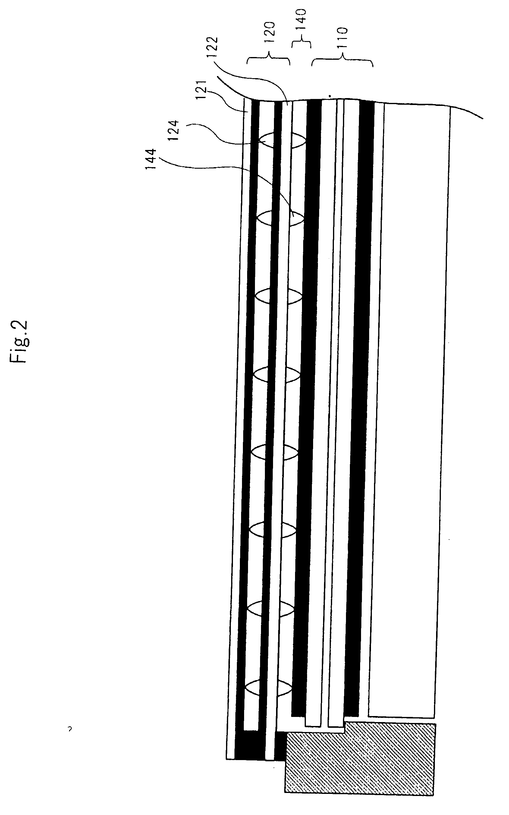
"The present invention provides a touch panel and a liquid crystal display apparatus that prevents interference fringes and sticking between the two without affecting the display performance of the liquid crystal display panel. This is achieved by placing a dot spacer on an inner transparent conductive film and disposing it on the display surface of the liquid crystal display panel via an air layer. Another dot spacer is placed on the air layer at a position that does not overlap with the first dot spacer within a predetermined viewing angle range. This configuration results in a thinner air layer and touch panel, reducing the overall thickness of the liquid crystal display apparatus."

Problems solved by technology

In such a case, in the liquid crystal display apparatus, interference fringes take place and a problem arises in that the display condition is impaired by the interference fringes.
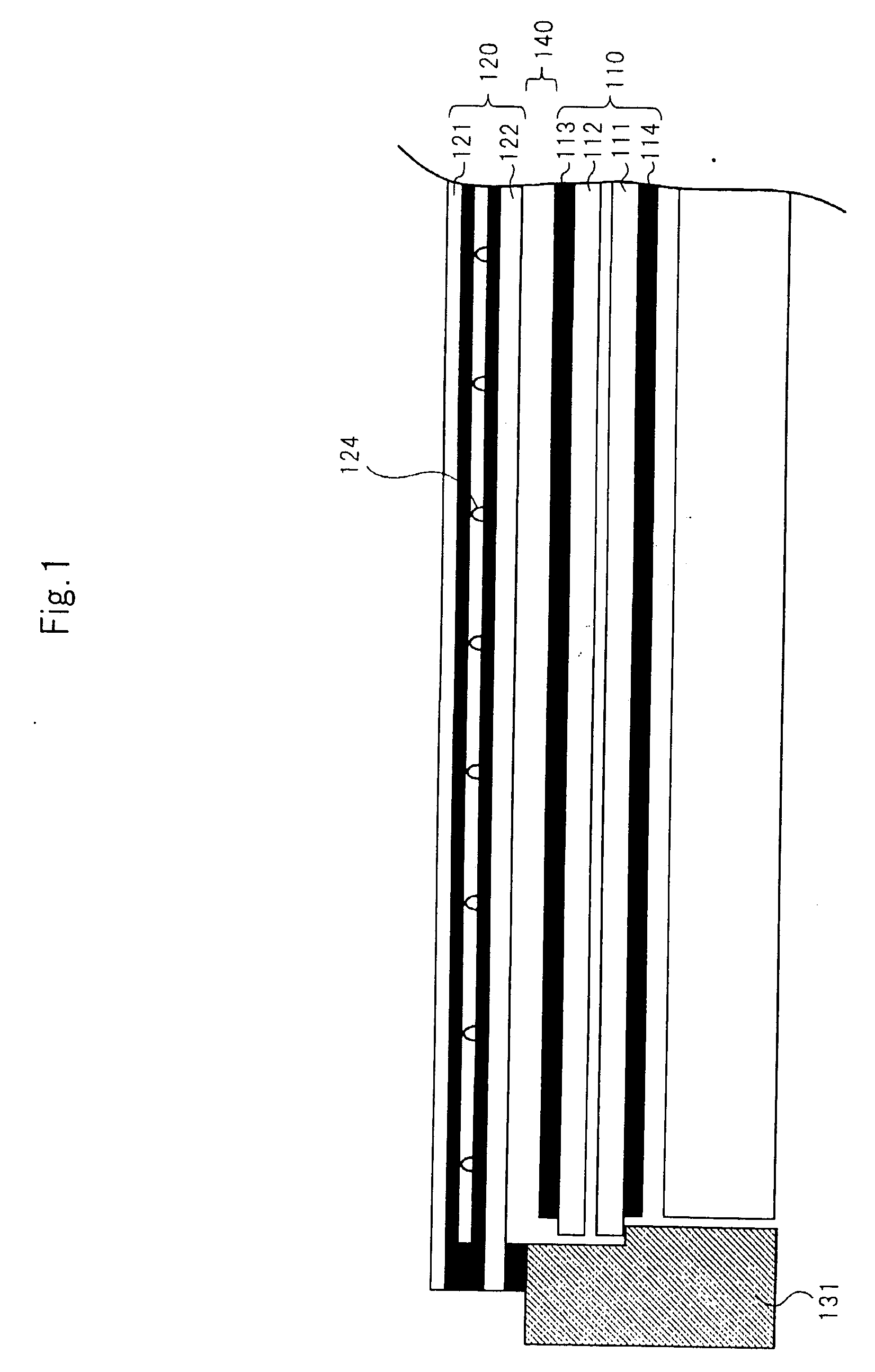
Further, there is also a case in which lower substrate 122 of touch panel 120 and polarizing plate 113 of liquid crystal display panel 110 come into contact and stick to each other resulting in a problem in which normal functions such as operation of the liquid crystal display apparatus cannot be performed.
Therefore, this configuration has a problem in that it is difficult to concurrently prevent the occurrence of interference fringes and to maintain display performance.
However, this configuration has a problem in that the manufacturing cost of a touch panel is high, the yield of a liquid crystal display apparatus in the manufacturing process is low, the initial cost for such equipment investment is high, and the load during the input operation is likely to propagate to the surface of the liquid crystal display panel.
Therefore, in this configuration, there are many problems such as that since display irregularities occur when the touch panel is pressed, it is necessary, as a countermeasure thereof, to improve the structure of the liquid crystal display panel.
However, in this configuration as well, there are many problems such as high manufacturing cost, low reliability and the like.
In such a configuration, although the sticking between the liquid crystal display panel and the touch panel and the occurrence of interference fringes may be solved, it is thought that the image quality performance and display performance of a liquid crystal display apparatus will be affected since degradations in display visibility and optical characteristics will be caused.
When a sample in which anti-glare processing is applied on the surface of the polarizing plate provided on the color filter substrate making up a liquid crystal display panel is actually fabricated and used, a problem occurs in which fine size characters displayed on the liquid crystal display apparatus are blurred and also in which degradation in contrast occurs in the result of an optical measurement, and in which the level at which actual use becomes possible is not been reached.
Accordingly, a problem remains in which a liquid crystal display apparatus inevitably has a large outer dimension in the thickness direction of the entire apparatus.
Therefore, it has been difficult to realize a liquid crystal display apparatus which maintains the display quality of a liquid crystal display apparatus, is inexpensive, and which can be downsized.

Method used


Image

  • Touch panel, liquid crystal display apparatus, and method for manufacturing thereof
  • Touch panel, liquid crystal display apparatus, and method for manufacturing thereof
  • Touch panel, liquid crystal display apparatus, and method for manufacturing thereof

Examples


second exemplary embodiment

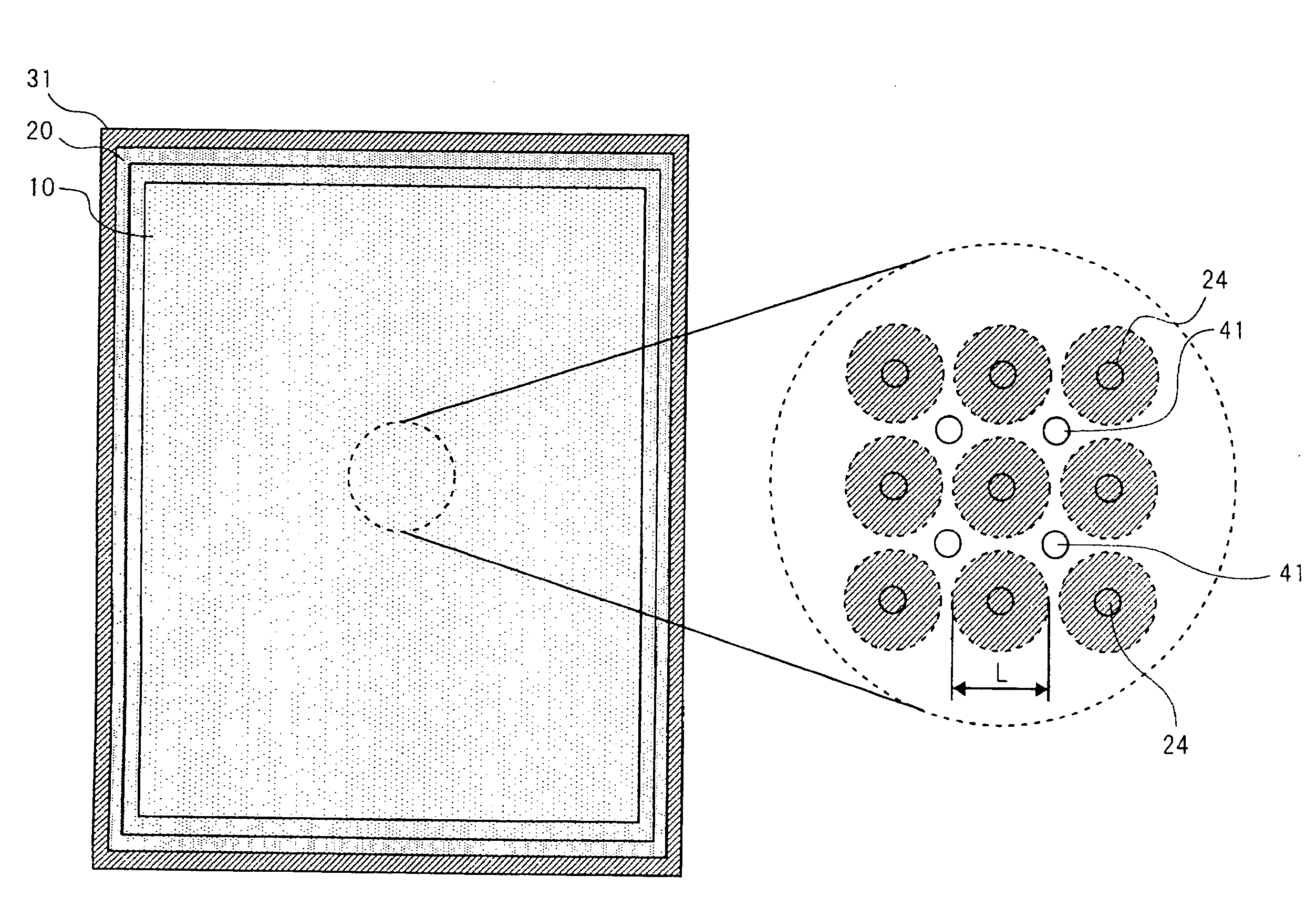
[0056]FIG. 8 shows the liquid crystal display apparatus of a second exemplary embodiment. The present exemplary embodiment is different from the first exemplary embodiment in that dot spacer 43 is formed on the surface of polarizing plate 13 included in color filter substrate 12 which makes up the liquid crystal display panel.

[0057]As shown in FIG. 8, projection-like dot spacers 43 of a predetermined size are formed in a regular arrangement on polarizing plate 13 on color filter substrate 12 by use of a printing and coating method onto the surface of polarizing plate 13 which is generally practiced in the manufacturing process of polarizing plate 13. Subsequently, polarizing plate 13 on which dot spacers 43 have been made is pasted onto color filter substrate 12 of liquid crystal display panel 10 to make up liquid crystal display panel 10. At this moment, dot spacer 43 that is to be formed on polarizing plate 13 is defined and processed so as to be disposed at a position where inter...


PUM


Abstract

The present invention is configured such that a touch panel has a dot spacer that is disposed on an inner transparent conductive film and that is disposed on a display surface of a liquid crystal display panel via an air layer. An another dot spacer is disposed on a surface of touch panel opposite to the display surface of the liquid crystal display panel at a position which does not overlap with the dot spacer within a predetermined view angle range on the display surface.

Description

BACKGROUND OF THE INVENTION[0001]1. Field of the Invention[0002]The present invention relates to a touch panel to be disposed on a liquid crystal display panel via an air layer, a liquid crystal display apparatus, and a method for manufacturing thereof.[0003]2. Description of the Related Art[0004]A liquid crystal display apparatus equipped with a touch panel is used in various fields such as POS (Point of Sales) terminals, ATMs (Automatic Teller Machines), ticket machines and car audio equipment. Moreover, a liquid crystal display apparatus equipped with a touch panel is utilized in wide fields such as PDAs (Personal Data assistants) and smartphones which also provide a telephone function. In such a kind of liquid crystal display apparatus, the load imposed by an input plane, which also serves as a display surface, includes load caused by an input operation. Further, in the case of a liquid crystal display apparatus which has an enhanced portability, there is for example a load impo...

Claims


Application Information

Patent Timeline
Patent Type & Authority Applications(United States)
IPC IPC(8): G06F3/041
CPCG02F1/13338G06F3/045G06F3/041G06F3/0412
Inventor TOYOMAKI, NAOHITO
Owner NEC LCD TECH CORP
Learn More