
Pipeline a/d converter and digital camera

a converter and digital camera technology, applied in the field of pipeline a/d converters, can solve the problems of increasing the size of the conversion portion used in the first stage, consuming a dominant amount of power of the operation amplifier in the respective stage, and avoiding an increase in the area of the element, suppressing an increase in the block area, and reducing power consumption

Active Publication Date: 2009-09-10
PANASONIC SEMICON SOLUTIONS CO LTD
View PDF7 Cites 0 Cited by
  • Summary
  • Abstract
  • Description
  • Claims
  • Application Information

AI Technical Summary

Benefits of technology

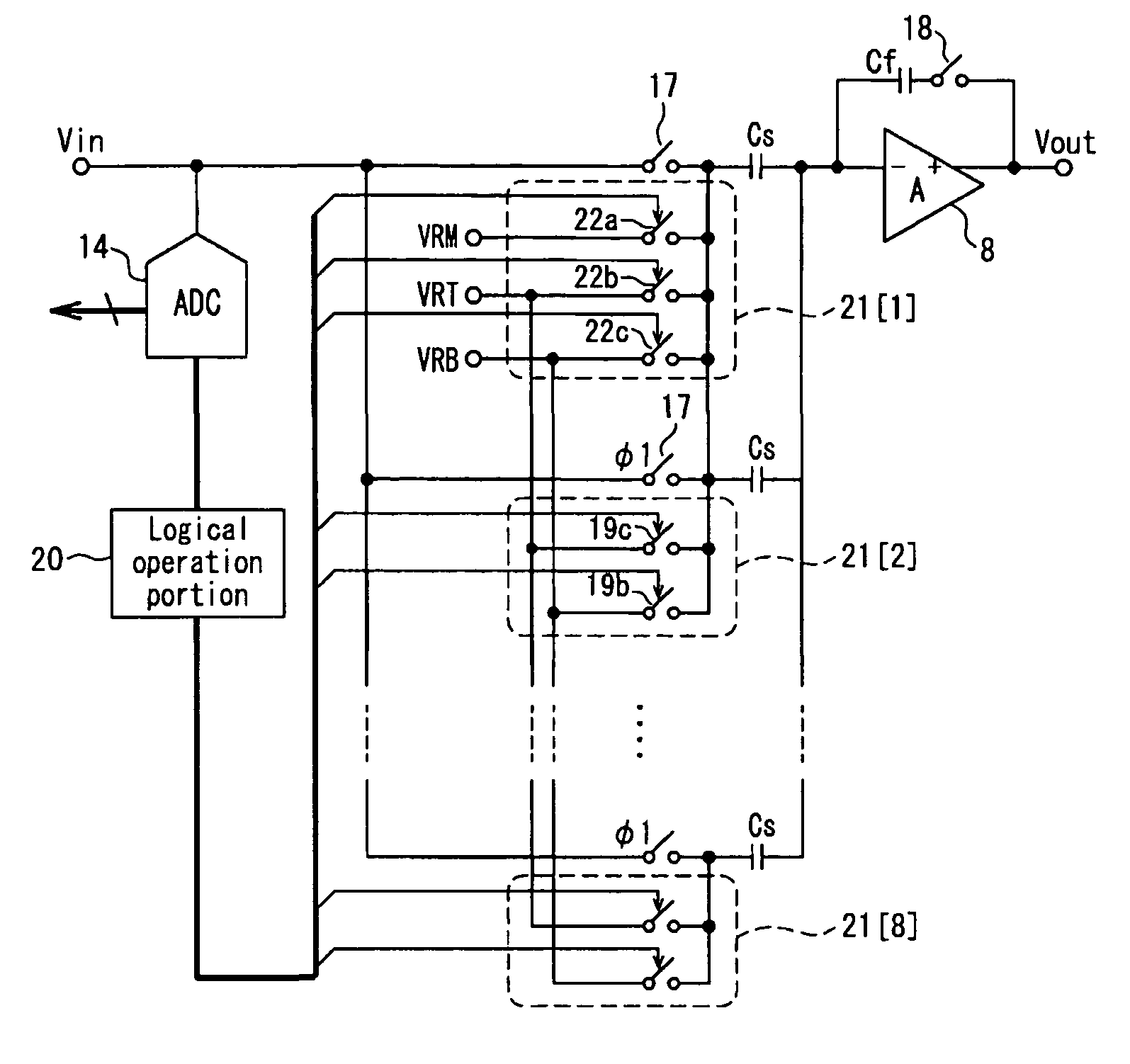
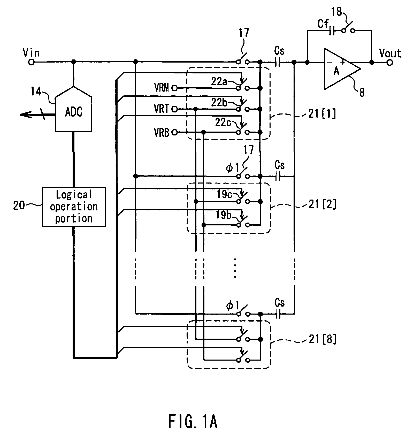
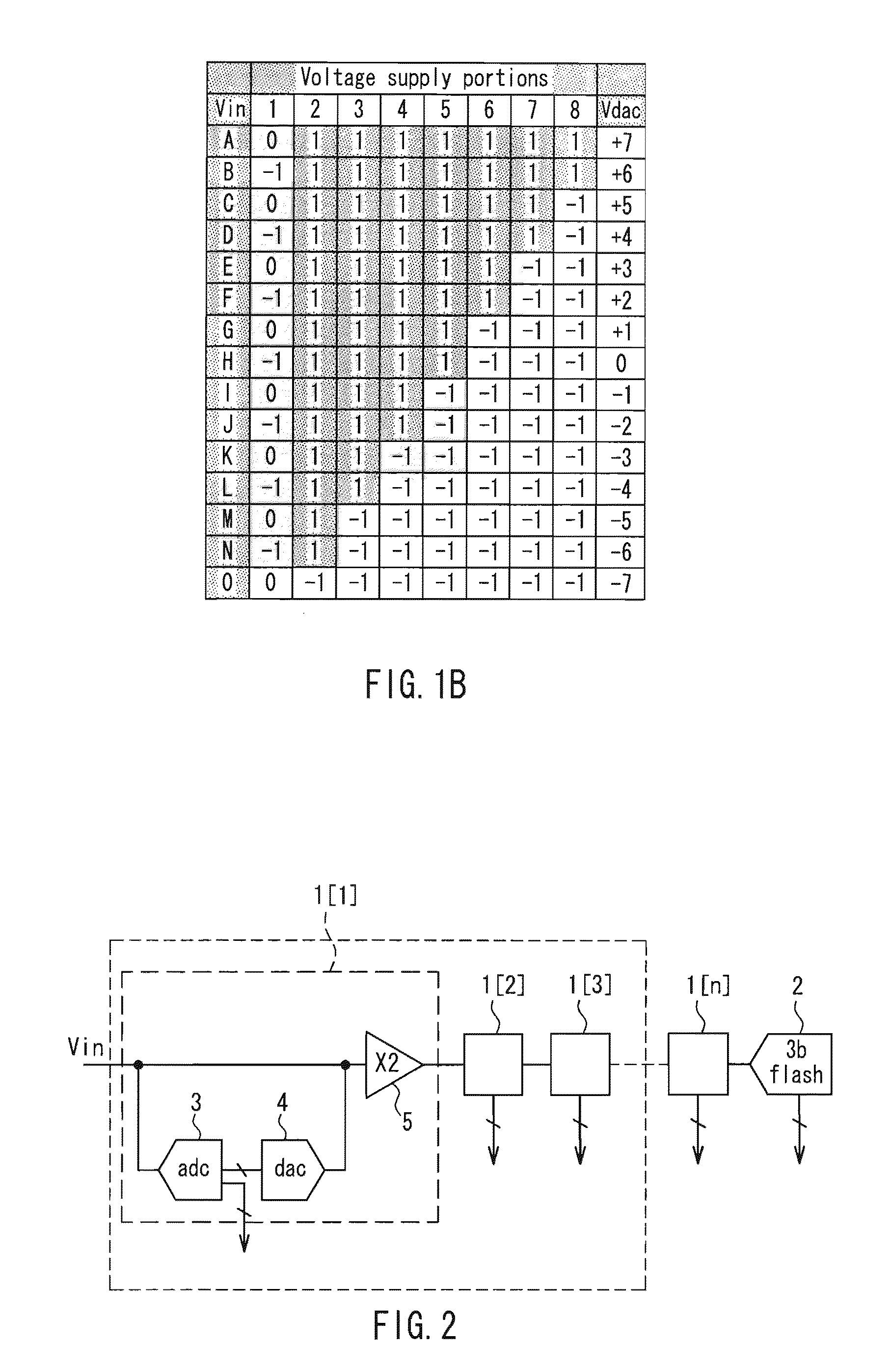
The present invention provides a pipeline A / D converter that can reduce power consumption while suppressing an increase in the area of an element. The converter has multiple stages connected in cascade, each performing A / D conversion for each part of bits. The first stage performs A / D conversion of a plurality of bits, using a combination of reference voltages generated from primary and auxiliary voltage supply portions. This reduces the number of operational amplifiers needed and avoids complicating the wiring and layout. The number of input capacitors is also reduced, resulting in a smaller capacitance value and suppressing an increase in the area of an element.

Problems solved by technology

In the pipeline structure, the operational amplifiers in the respective stages consume a dominant amount of power.
However, when the first stage has a multi-bit configuration, the DA conversion portion used in the first stage becomes exponentially larger in size.
Accordingly, the DA conversion portion becomes exponentially larger, which leads to disadvantages such as an increase in the area of an element, an increase in the complexity of wiring, and difficulty in routing wiring in a layout.
When one unit of the capacitors is small in size, relative accuracy decreases, which appears as an error of the pipeline A / D converter.

Method used


Image

  • Pipeline a/d converter and digital camera
  • Pipeline a/d converter and digital camera
  • Pipeline a/d converter and digital camera

Examples


Embodiment Construction

[0041]Based on the above-described configuration, the pipeline A / D converter of the present invention may have the following aspects.

[0042]More specifically, the reference voltage at the auxiliary level may be set at a level between the plurality of levels of the reference voltage to be output from the primary voltage supply portions.

[0043]Further, the reference voltage to be output from the auxiliary voltage supply portion may include a reference voltage at least one of the plurality of levels of the reference voltage to be output from the primary voltage supply portions, in addition to the reference voltage at the auxiliary level.

[0044]Further, the primary voltage supply portions may output the reference voltage at either of two levels, that is, a high-potential level and a low-potential level, and the reference voltage to be output from the auxiliary voltage supply portion may include the reference voltage at the auxiliary level between the high-potential level and the low-potent...


PUM


Abstract

In each of a plurality of stages, an input analog signal is quantized, so that a digital signal corresponding to each part of bits is generated. A DA conversion portion generates an analog reference signal based on the digital signal, and a remainder operation portion performs addition / subtraction and amplification by a predetermined factor with respect to the input analog signal. Then, the signal thus obtained is supplied to a subsequent stage. The DA conversion portion in the first stage where A / D conversion of a plurality of bits is performed includes primary voltage supply portions capable of outputting a reference voltage at one of a plurality of levels, and an auxiliary voltage supply portion capable of outputting a reference voltage at an auxiliary level different from the above-described level. The respective voltage supply portions selectively output the reference voltages based on a digital signal generated by an AD conversion portion. Based on a combination of the output reference voltages, the analog reference signal in accordance with the digital signal is generated. It is possible to reduce power consumption while suppressing an increase in the area of an element.

Description

BACKGROUND OF THE INVENTION[0001]1. Field of the Invention[0002]The present invention relates to a pipeline A / D converter that converts an analog input signal into a digital signal in descending order of bit significance by using a plurality of stages, each of which quantizes the analog input signal so as to generate the digital signal.[0003]2. Description of Related Art[0004]As digitization proceeds in the fields of audiovisual, telecommunication, and the like, it has been required for A / D converters used as key devices in these fields to achieve higher speed and higher resolution. Pipeline A / D converters recently have been used frequently as circuits that are excellent in terms of high speed and power consumption. However, as CCD cameras have an increasing number of pixels, for example, pipeline A / D converters that are excellent in terms of high speed and power consumption also are required to achieve much higher speed and lower power consumption.[0005]FIG. 2 is a block diagram sh...

Claims


Application Information

Patent Timeline
Patent Type & Authority Applications(United States)
IPC IPC(8): H04N5/228H03M1/12H04N23/40
CPCH03M1/167H04N5/37455H04N5/355H04N5/335H04N25/57H04N25/00H04N25/78H04N25/772
Inventor KITO, TAKAYASUOGITA, SHINICHI
Owner PANASONIC SEMICON SOLUTIONS CO LTD
Learn More