Exposure apparatus, exposure method, and device manufacturing method

a technology of exposure apparatus and manufacturing method, which is applied in the direction of photomechanical treatment, printing, instruments, etc., can solve the problems of unnecessary operations such as full recovery and re-supply of liquid in the liquid immersion area, and achieve the effect of improving throughput and shortening the movement stroke of both the movable bodies

Inactive Publication Date: 2009-09-10
NIKON CORP
View PDF31 Cites 38 Cited by
  • Summary
  • Abstract
  • Description
  • Claims
  • Application Information

AI Technical Summary

Benefits of technology

[0012]With this apparatus, by moving the first and second movable bodies in the first direction while maintaining the scrum state of the first and second movable bodies, the liquid immersion area can be delivered between both the movable bodies without leaking the liquid from between both the movable bodies. Accordingly, operations such as full recovery and re-supply of the liquid of the liquid immersion area become unnecessary. Further, compared with the case where the first and second movable bodies are made to approach or come into contact in the second direction, a movement distance (a movement stroke) of both the movable bodies can be shortened. Further, by making both the movable bodies be in proximity or in contact via respective parts of their facing surfaces in the first direction in a state of being shifted in the second direction, the movement stroke of both the movable bodies can be further shortened. Consequently, the throughput can be improved.
[0014]With this method, during the transition from the first state where one of the movable bodies is located in the first area to the second state where the other of the movable bodies is located in the first area, the first movable body and the second movable body are simultaneously driven in the first direction while keeping the scrum state where the first and second movable bodies are shifted in the second direction and are in proximity or in contact in the first direction, and the liquid immersion area is delivered from one of the movable bodies to the other of the movable bodies. Accordingly, it becomes possible to deliver the liquid immersion area between both the movable bodies without leaking the liquid from between both the movable bodies. Consequently, operations such as full recovery and re-supply of the liquid of the liquid immersion area become unnecessary. Further, compared with the case where the first and second movable bodies are made to approach or come into contact in the second direction, a movement distance (a movement stroke) of both the movable bodies, which is required when moving the movable bodies into the scrum state, can be shortened. Further, by making both the movable bodies be in proximity or in contact in the first direction in a state of being shifted in the second direction, the movement stroke of both the movable bodies can be further shortened. Therefore, the throughput can be improved.

Problems solved by technology

Accordingly, operations such as full recovery and re-supply of the liquid of the liquid immersion area become unnecessary.
Consequently, operations such as full recovery and re-supply of the liquid of the liquid immersion area become unnecessary.

Method used


Image

  • Exposure apparatus, exposure method, and device manufacturing method
  • Exposure apparatus, exposure method, and device manufacturing method
  • Exposure apparatus, exposure method, and device manufacturing method

Examples


Embodiment Construction

[0032]An embodiment of the present invention is described below, with reference to FIGS. 1 to 12.

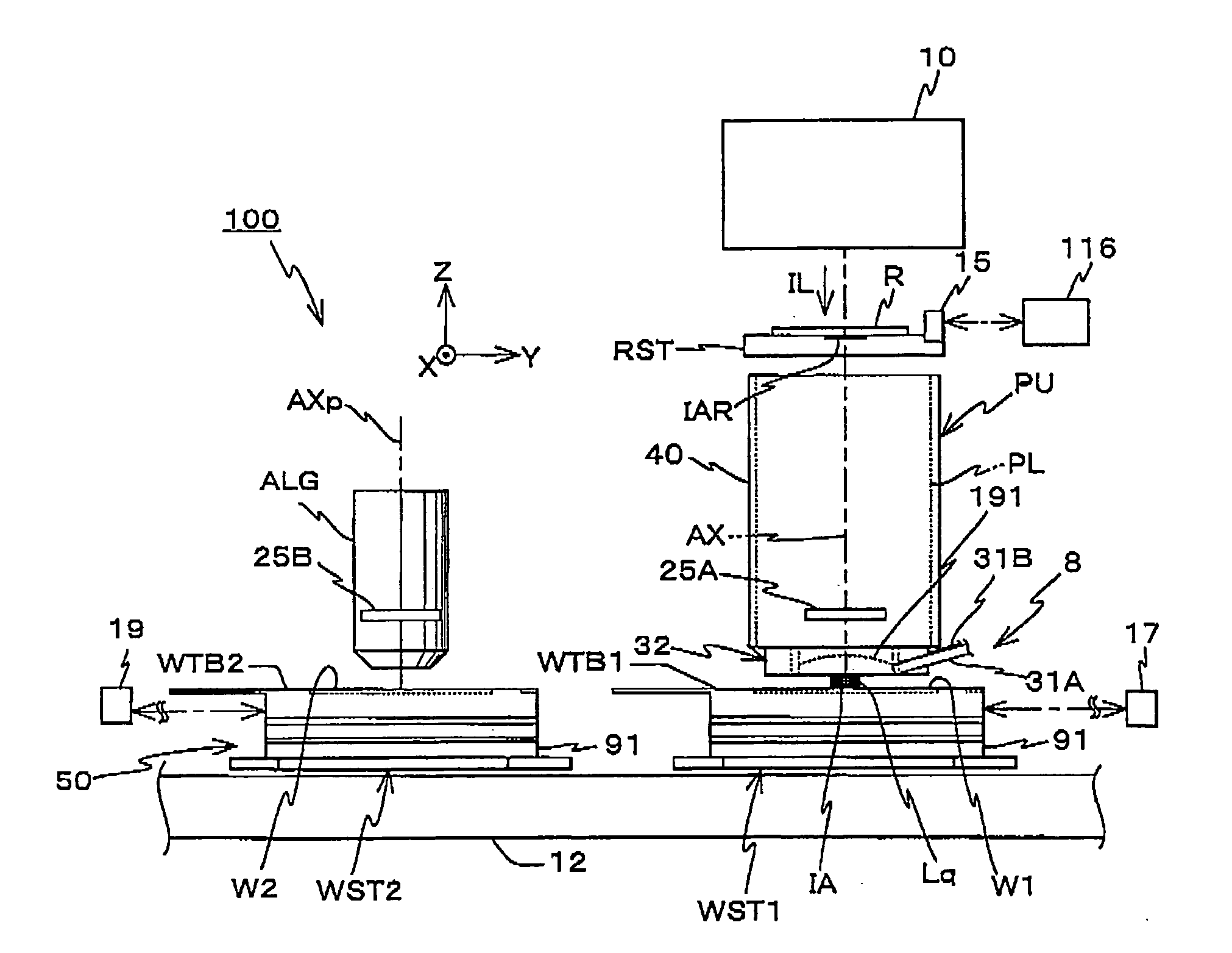
[0033]FIG. 1 schematically shows a configuration of a twin-stage-type exposure apparatus 100 related to the embodiment. Exposure apparatus 100 is a projection exposure apparatus by a step-and-scan method, which is a so-called scanner. As is described later on, in the embodiment, a projection optical system PL and an alignment system ALG are arranged, and the following explanation will be given assuming that a direction parallel to an optical axis AX of projection optical system PL is a Z-axis direction, a direction parallel to a straight line that connects the center (optical axis AX) of projection optical system PL and the detection center (an optical axis AXp) of alignment system ALG within a plane orthogonal to the Z-axis direction is a Y-axis direction, a direction orthogonal to a Z-axis and a Y-axis is an X-axis direction, and rotation (inclination) directions about the X-axis, the ...


PUM


Abstract

During the transition from a state where one of wafer stages is located in an area below a projection optical system where a liquid immersion area is formed to a state where the other of the wafer stages is located in the area, both the wafer stages are made to be in proximity or in contact in a Y-axis direction in a state of being shifted in an X-axis direction, by making an overhang section and a stepped section that are arranged respectively on the wafer stages be engaged, and both the wafer stages are simultaneously driven in the Y-axis direction while maintaining this state. Accordingly, the liquid immersion area is delivered between the two wafer stages via the overhang section and leakage of a liquid that forms the liquid immersion area is restrained.

Description

CROSS-REFERENCE TO RELATED APPLICATIONS[0001]This non-provisional application claims the benefit of Provisional Application No. 60 / 996,798 filed Dec. 5, 2007, the disclosure of which is hereby incorporated herein by reference in its entirety.BACKGROUND OF THE INVENTION[0002]1. Field of the Invention[0003]The present invention relates to exposure apparatuses, exposure methods and device manufacturing methods, and more particularly, to an exposure apparatus and an exposure method used in a lithography process for manufacturing microdevices such as semiconductor devices, and a device manufacturing method using the exposure method.[0004]2. Description of the Background Art[0005]Conventionally, in a lithography process for manufacturing electron devices (microdevices) such as semiconductor devices (such as integrated circuits) and liquid crystal display devices, an exposure apparatus such as a projection exposure apparatus by a step-and-repeat method (a so-called stepper), or a projectio...

Claims


Application Information

Patent Timeline
Patent Type & Authority Applications(United States)
IPC IPC(8): G03B27/52
CPCG03F7/70341G03F7/70775G03F7/70733
Inventor SHIBAZAKI, YUICHI
Owner NIKON CORP
Why Eureka
Try Eureka