Motion artifacts less electrode for bio-potential measurements and electrical stimulation, and motion artifacts less skin surface attachable sensor nodes and cable system for physiological information measurement and electrical stimulation

a technology of biopotential monitoring and motion artifacts, which is applied in the field of biopotential electrodes and biopotential electrode caballing systems, can solve the problems of bulky caballing systems and connectors, motion artifacts of biopotential monitoring systems mainly occurring, etc., and achieve the effect of reducing motion artifacts and improving signal-to-noise ratio

Inactive Publication Date: 2009-09-10
WIJESIRIWARDANA RAVINDRA
View PDF4 Cites 27 Cited by
  • Summary
  • Abstract
  • Description
  • Claims
  • Application Information

AI Technical Summary

Benefits of technology

[0009]The present invention is a new motion artifact less bio-potential electrode and a bio potential electrodes caballing system that will reduce the motion artifacts and hence improve the signal to noise ratio.

Problems solved by technology

The motion artifacts of the bio potential monitoring systems mainly occur due to the relative motion of the electrode against the skin.
This is further exaggerated by the bulky caballing systems and connectors that connect these electrodes to the external monitoring systems.

Method used


Image

  • Motion artifacts less electrode for bio-potential measurements and electrical stimulation, and motion artifacts less skin surface attachable sensor nodes and cable system for physiological information measurement and electrical stimulation
  • Motion artifacts less electrode for bio-potential measurements and electrical stimulation, and motion artifacts less skin surface attachable sensor nodes and cable system for physiological information measurement and electrical stimulation
  • Motion artifacts less electrode for bio-potential measurements and electrical stimulation, and motion artifacts less skin surface attachable sensor nodes and cable system for physiological information measurement and electrical stimulation

Examples


Embodiment Construction

. 1A, FIG. 1B, FIG. 2A, FIG. 2B, FIG. 3A, FIG. 3B, FIG. 3C, FIG. 4A, FIG. 4B

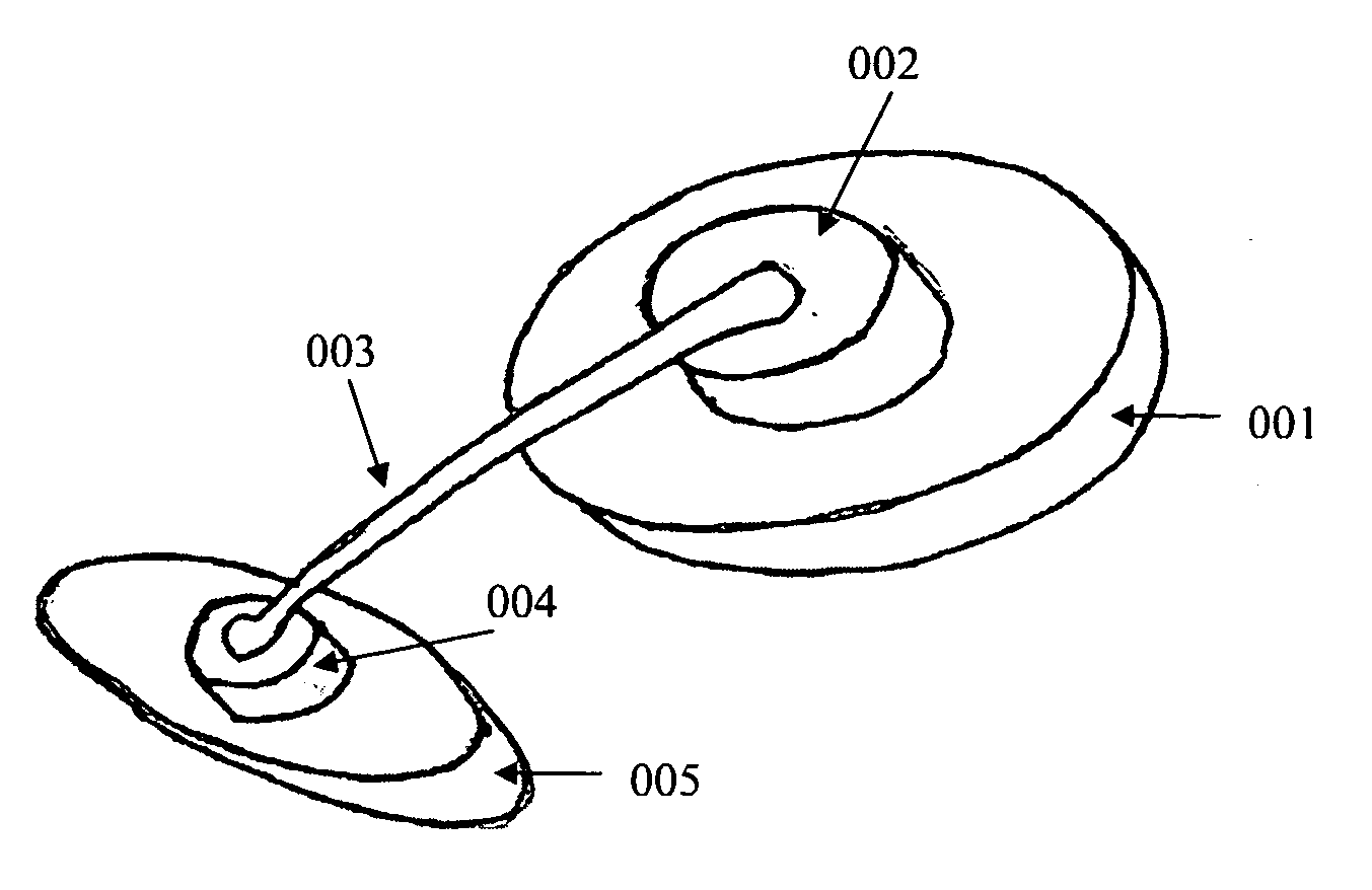
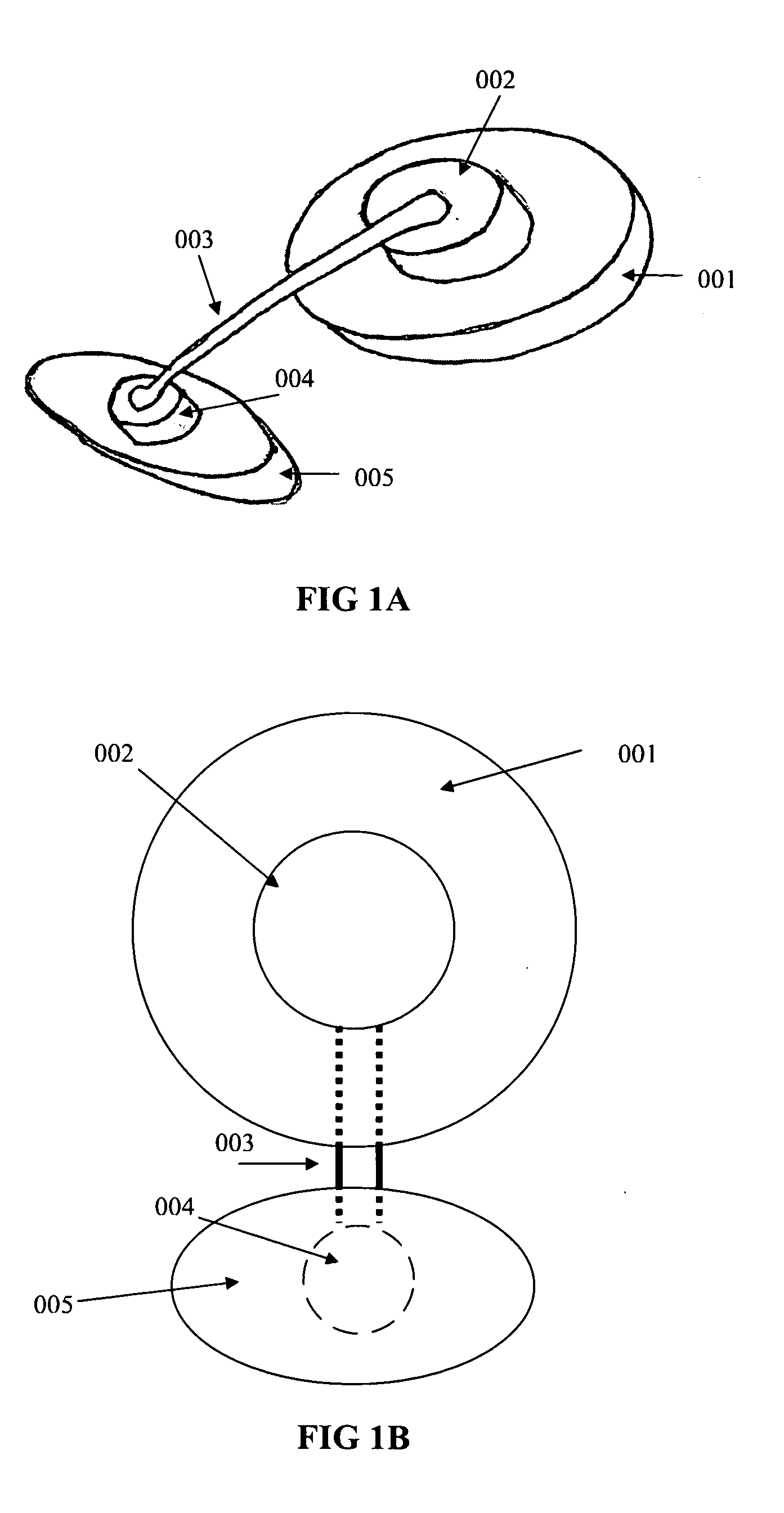
[0050]FIG. 1A and FIG. 1B show the first arrangement of the electrode. The electrode (002) is connected to a substrate (001) that can be attached on to the skin of the wearer. The electrode is connected to the lead connector (004) via the electrically conductive wire (003). The lead connector (004) is on a separate substrate (005). The external electrical cable / s is connected to this lead connector.

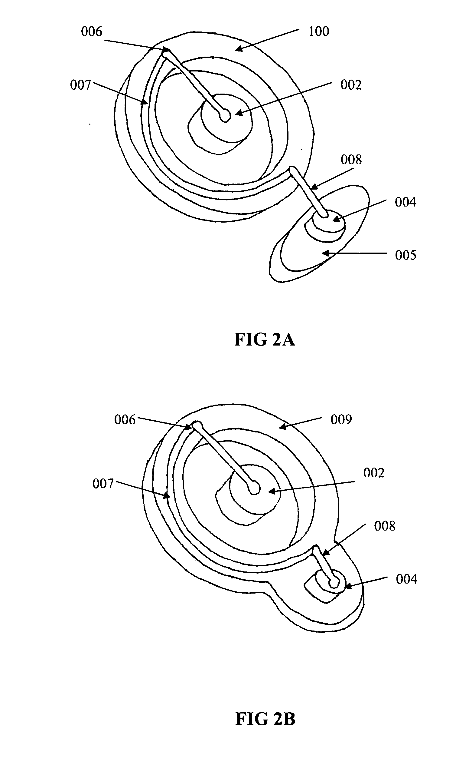
[0051]FIG. 2A shows the second arrangement of the electrode. The electrode (002) is not in the same substrate as the ring substrate (100). The electrode is a sticky electrode and the ring substrate is also a sticky substrate. The electrode is surrounded by the ring substrate (100). The lead connector (004) of the electrode is on a separate sticky substrate (005). Electro conductive path ways connect the lead connector (005) and the electrode (002). Part of this conductive pathway is on the ring substrate (100).

[00...


PUM


Abstract

Motion artifacts less electrode for bio-potential measurements and electrical stimulation is discussed under the present invention. Three different arrangements of the electrode are introduced. Further the electrode embodiments are generalized for reducing motion artifacts of any skin contact senor or an actuator embodiment. In addition a piggy backed daisy chained sensor nodes or actuator nodes cabling system is introduced to minimize the motion artifacts further. A PPG sensor is constructed according to the generalized sensor embodiment and this PPG sensor is used for constructing an ear wearable heart rate monitoring unit. Moreover an ear wearable EEG monitoring system based on piggy backed daisy chained sensor or actuator nodes and caballing arrangement is illustrated.

Description

CROSS-REFERENCE TO RELATED APPLICATIONS[0001]This application claims the benefit of provisional patent application Ser. No. 61 / 033,841, filed Mar. 5, 2008 by the present inventor.FEDERALLY SPONSORED RESEARCH [0002]Not ApplicableSEQUENCE LISTING OR PROGRAM [0003]Not ApplicableBACKGROUND[0004]1. Field[0005]This application relates to bio-potential electrodes and bio-potential electrodes caballing systems[0006]2. Prior Art[0007]One of the major problems of bio-potential electrodes used today is their vulnerability to the motion artifacts. This is one of the major drawbacks in patient monitoring units, rehab units, sports and health information monitoring systems. In addition when a patient or a wearer is moving the signal to noise ratio of the bio potential signals captured by these electrodes reduces due to motion artifacts. Therefore the fidelity, accuracy and reliability of the electro cardiogram (ECG), electromyogram (EMG) and electro encephalogram (EEG) signals that are measured u...

Claims


Application Information

Patent Timeline
Patent Type & Authority Applications(United States)
IPC IPC(8): A61M35/00A61B5/04A61B5/00A61F7/00
CPCA61B5/02416A61B5/0408A61B5/0448A61B5/0492A61F7/00A61B5/6815A61B5/6833A61B5/7207A61B2560/0412A61B5/4362A61B5/25A61B5/288A61B5/296
Inventor WIJESIRIWARDANA, RAVINDRA
Owner WIJESIRIWARDANA RAVINDRA
Why Eureka
Try Eureka