Variable valve actuation system of internal combustion engine and control apparatus of internal combustion engine

a technology of internal combustion engine and variable valve actuation, which is applied in the direction of electrical control, process and machine control, etc., can solve the problems of difficult to ensure the sufficiently enhanced acceleration response and difficult to provide a sufficient vehicle acceleration response, so as to enhance the transient acceleration responsiveness as well as the transient engine torque increase, enhance the transient acceleration responsiveness and the effect of transien

Active Publication Date: 2009-09-10
HITACHI ASTEMO LTD
View PDF8 Cites 58 Cited by
  • Summary
  • Abstract
  • Description
  • Claims
  • Application Information

AI Technical Summary

Benefits of technology

[0007]Accordingly, in the internal combustion engine with a mechanical supercharging device, it is desirable to enhance a transient acceleration responsiveness as well as a transient engine-torque-increase responsiveness, when accelerating the vehicle from a non-load state (e.g., an idling state) or a light load state.
[0008]It is, therefore, in view of the previously-described disadvantages

Problems solved by technology

However, when quickly accelerating the vehicle from a non-load state (e.g., an idling state) or a light load state, in other words, when a rapid engine load rise occurs, it is difficult to provide a sufficient vehicle-acceleration response in the case of an internal combus

Method used


Image

  • Variable valve actuation system of internal combustion engine and control apparatus of internal combustion engine
  • Variable valve actuation system of internal combustion engine and control apparatus of internal combustion engine
  • Variable valve actuation system of internal combustion engine and control apparatus of internal combustion engine

Examples


first embodiment

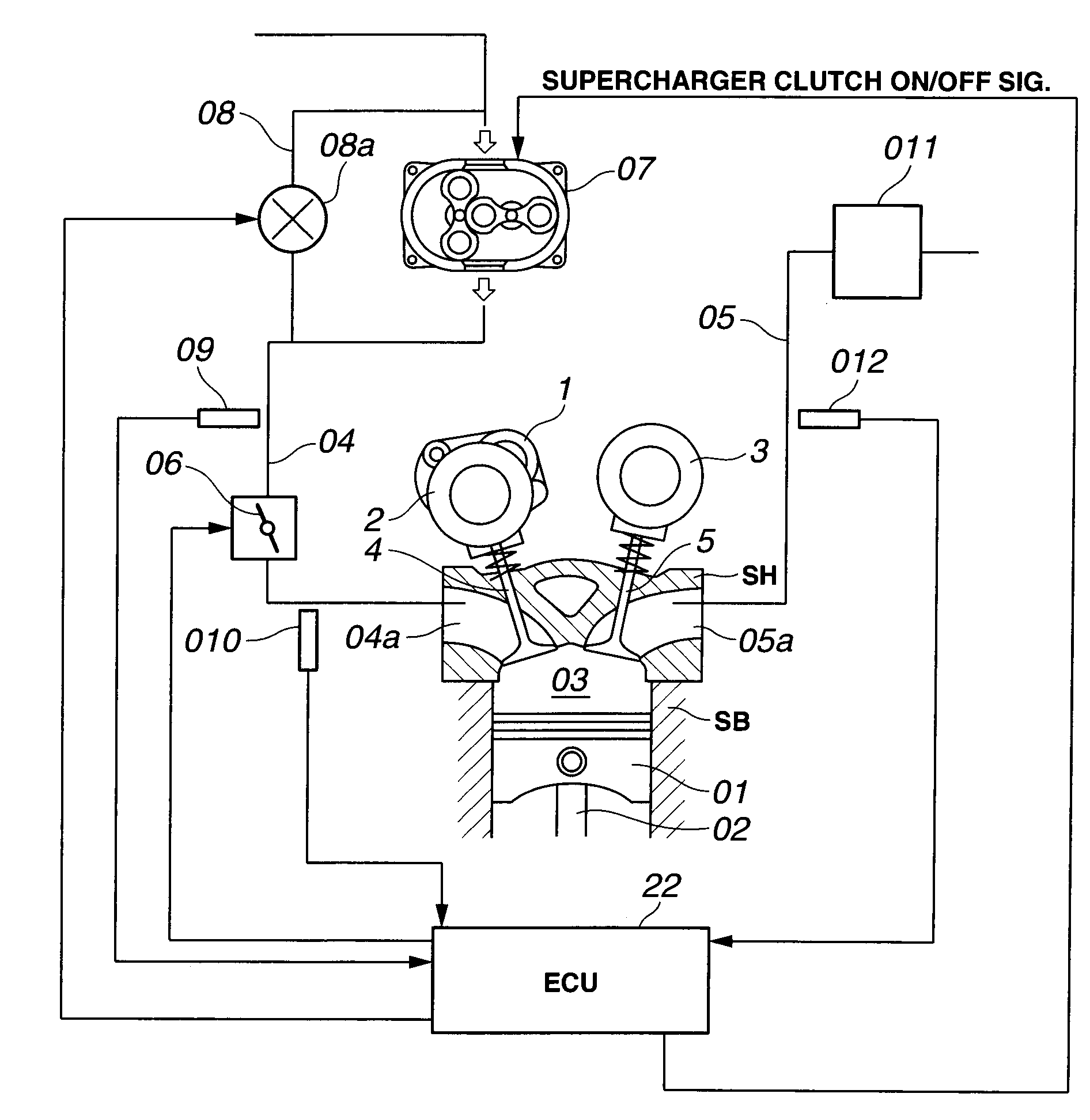
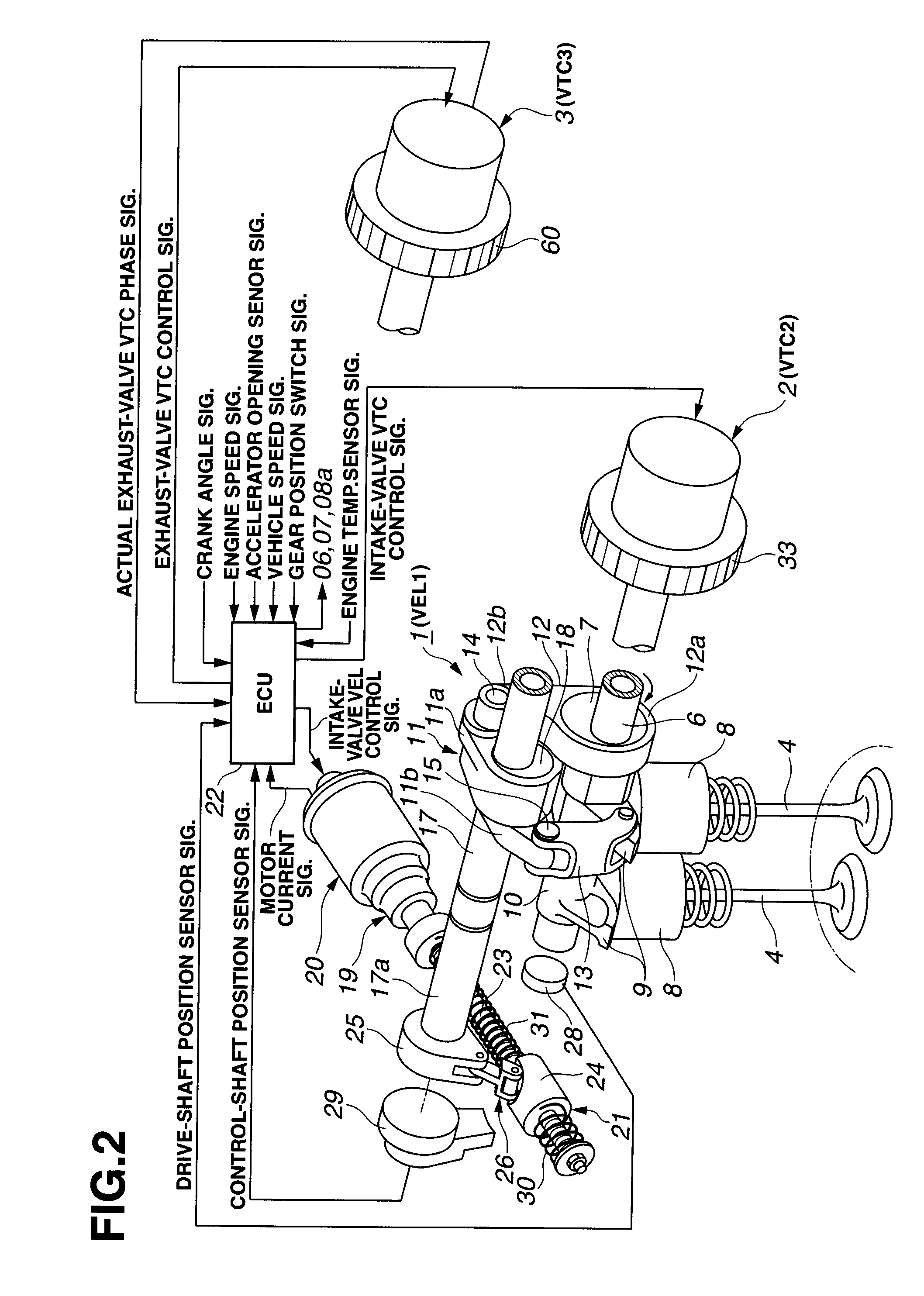
[0038]Referring now to the drawings, particularly to FIG. 1, the variable valve actuation system and the engine control apparatus of the first embodiment is exemplified in a supercharged, four-cycle internal combustion engine.

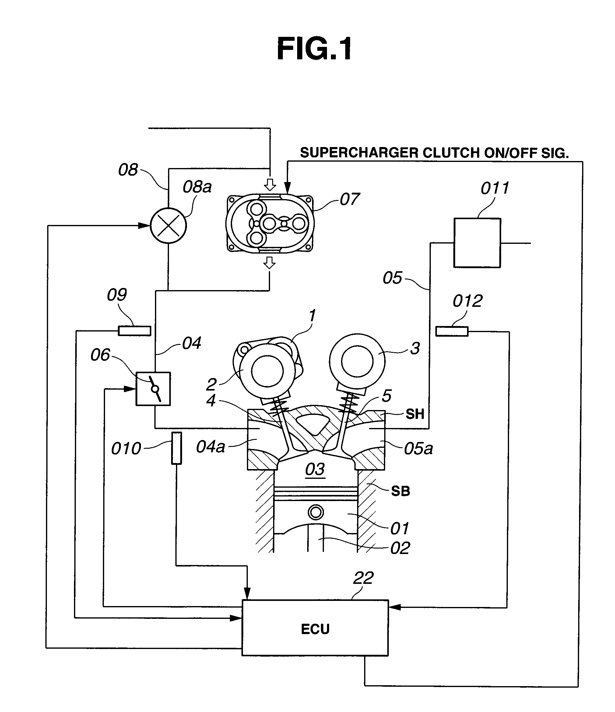
[0039]As can be appreciated from the system diagram of FIG. 1, the internal combustion engine has four valves for each cylinder, namely, two intake valves 4, 4 and two exhaust valves 5, 5 per one cylinder. An intake-valve variable valve event and lift (VEL) mechanism 1 (or an intake-valve variable lift mechanism VEL1) and an intake-valve variable phase control mechanism or an intake-valve valve timing control (VTC) mechanism 2 (or an intake-valve variable phase-angle mechanism VTC2) are installed on one axial end of an intake-valve drive shaft 6 (described later), which is rotatably supported on an engine cylinder head SH. The intake-valve VEL mechanism 1 is provided for variably controlling or adjusting a valve lift amount and a working angle of each of intake...

second embodiment

[0154]Referring now to FIG. 14, there is shown the supercharged engine control routine, executed by the controller incorporated in the system of the second embodiment, after the engine has been started. The system of the second embodiment slightly differs from that of the first embodiment, in that valve-overlap control (valve-overlap enlargement control) is achieved by exhaust valve closure timing EVC control (EVC phase-retard control) via the exhaust-valve VTC mechanism 3.

[0155]The control routine of FIG. 14 (the second embodiment) is somewhat different from the control routine of FIG. 10 (the first embodiment), in that steps S1-S6, S9-S10, S12-S14, and S16-S17 included in the routine shown in FIG. 10 are identical to respective steps S21-S26, S29-S30, S32-S34, and S36-S37 included in the routine shown in FIG. 14, but steps S7-S8, S11, and S15 included in the routine shown in FIG. 10 are replaced with steps S27-S28, S31, and S35 included in the routine shown in FIG. 14.

[0156]As see...

third embodiment

[0173]Referring now to FIG. 16, there is shown the supercharged engine control routine, executed by the controller incorporated in the system of the third embodiment, after the engine has been started. The system of the third embodiment slightly differs from that of the first embodiment, in that valve-overlap control (valve-overlap enlargement control) is achieved by intake valve open timing IVO control (IVO phase-advance control) via the intake-valve VTC mechanism 2 and exhaust valve closure timing EVC control (EVC phase-retard control) via the exhaust-valve VTC mechanism 3, so as to realize the more enhanced absolute engine power output (a high-performance supercharged engine) in a high engine speed range.

[0174]The control routine of FIG. 16 (the third embodiment) is somewhat different from the control routine of FIG. 10 (the first embodiment), in that steps S1-S4, S6, S12, and S16-S17 included in the routine shown in FIG. 10 are identical to respective steps S41-S44, S46, S50, an...


PUM


Abstract

In a control apparatus of a supercharged internal combustion engine, a variable valve actuation system interacts with an engine control system. A controller is configured or programmed to increase an intake-valve lift by a variable valve lift mechanism, which is provided for variably controlling at least the intake-valve lift of engine valves, when starting from a vehicle stand-still state or when accelerating from an idling state or a light load state. The controller is further configured or programmed to increase a valve overlap of intake and exhaust valves by a variable phase control mechanism, which is provided for variably phase-shifting a central phase angle of a valve lift characteristic curve of at least one of the intake and exhaust valves, while increasing a boost pressure of intake air introduced into an engine cylinder by a supercharging device, after the intake-valve lift has been increased.

Description

TECHNICAL FIELD[0001]The present invention relates to a variable valve actuation system of an internal combustion engine employing a variable valve event and lift (VEL) mechanism, a variable phase control mechanism (a valve timing control (VTC) mechanism) and a supercharging device, and specifically to a control apparatus configured to enhance an acceleration responsiveness of the supercharged engine by controlling the VEL and VTC mechanisms, when accelerating an automotive vehicle.BACKGROUND ART[0002]In recent years, there have been proposed and developed various supercharged internal combustion engines capable of increasing an engine torque by supercharging intake air by means of a supercharging device installed in the intake system. One such supercharged engine has been disclosed in Japanese Patent Provisional Publication No. 2-119641 (hereinafter is referred to as “JP02-119641”).[0003]The supercharged engine of JP02-119641 also employs a variable phase control mechanism (a VTC m...

Claims


Application Information

Patent Timeline
IPC IPC(8): F02D43/00
CPCF01L1/022Y02T10/18F01L13/0026F01L2001/0475F01L2001/0537F01L2001/34469F01L2001/34483F01L2013/0073F01L2800/00F02D13/0219F02D13/023F02D13/0261F02D41/0007F02D41/10F02D2013/0292F02D2041/002F02D2250/21Y02T10/144F01L1/3442Y02T10/12
Inventor NAKAMURA, MAKOTO
Owner HITACHI ASTEMO LTD
Why Eureka
Try Eureka