Engine hydraulic control apparatus

a hydraulic control and engine technology, applied in mechanical devices, machines/engines, auxilaries, etc., can solve the problems of increasing the load applied to the oil pump, deteriorating startup characteristics, and inability to reach the flywheel, so as to reduce the load of the oil pump and reduce friction

Inactive Publication Date: 2009-09-17
TOYOTA JIDOSHA KK
View PDF3 Cites 27 Cited by
  • Summary
  • Abstract
  • Description
  • Claims
  • Application Information

AI Technical Summary

Benefits of technology

[0020]According to the present invention, because the valve opening pressure Qb of the relief valve is set to a valve opening pressure that is within a range of necessary hydraulic pressure that can ensure the necessary amount of oil that is required to lubricate the engine and is lower than the valve opening pressure Qa of the piston jets, the relief valve opens before oil is injected by the piston jets when the hydraulic pressure rises accompanying the viscosity of the oil becoming high during a cold startup of the engine, and it is possible to realize a reduction in the friction and a reduction in the load of the oil pump by reducing the hydraulic pressure and to avoid carrying out the injection of oil even though the temperature is low.

Problems solved by technology

However, because the viscosity of the oil becomes high when the temperature is low, the load that is applied to the oil pump increases because the flow resistance of the oil that is flowing through the oil passage increases, and this acts as a reactive force against the starter motor drive power.
Thus, the flywheel cannot be made to reach the minimum speed that enables the engine to be started up, and this may cause the startup characteristics to deteriorate.

Method used


Image

  • Engine hydraulic control apparatus
  • Engine hydraulic control apparatus
  • Engine hydraulic control apparatus

Examples


first embodiment

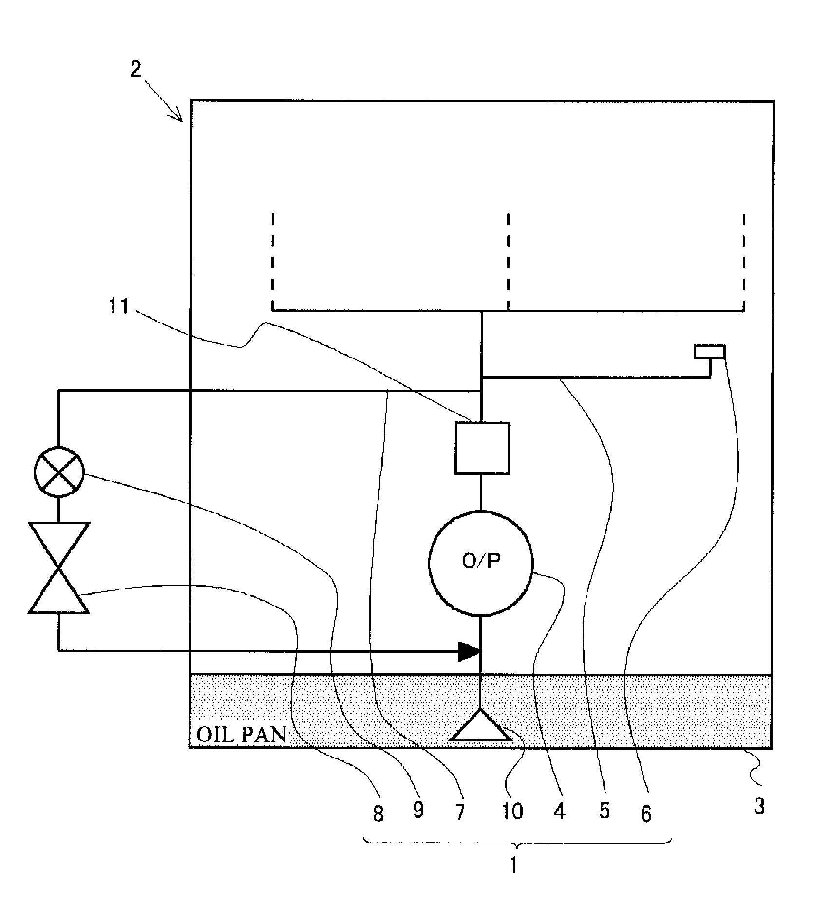
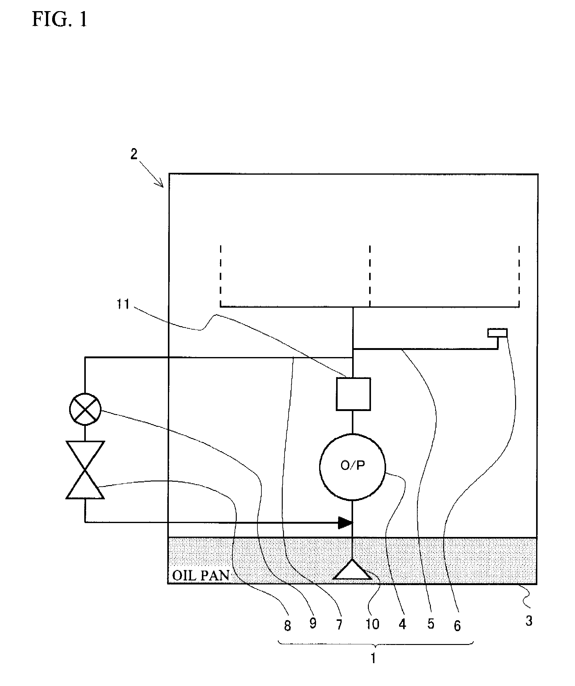
[0028]FIG. 1 is a schematic drawing that shows the schematic structure of an engine 2 that incorporates the hydraulic control apparatus 1 of the present invention. The hydraulic control apparatus 1 includes an oil pump 4 that draws oil from an oil pan 3 due to the rotation of the crankshaft; a piston jet 6 that opens when the hydraulic pressure of the oil that has been drawn by this oil pump 4 attains a valve opening pressure Qa and injects oil towards a piston (not illustrated) through an oil injection path 5; a relief valve 8 that is disposed on an oil return path 7 that is different from the oil injection path 5, and is opened when the hydraulic pressure of the oil that has been drawn by the oil pump 4 attains a valve opening pressure Qb; and a switching valve 9 that is disposed on the oil return path 7. The oil pan 3 corresponds to the oil tank in the present invention. A strainer 10 is disposed on the upstream end portion of the oil pump 4. In addition, the downstream end of th...

second embodiment

[0036]Next, a second embodiment of the present invention will be explained with reference to FIG. 4. The point on which a hydraulic control apparatus 20 that is shown in FIG. 4 differs from the hydraulic control apparatus 1 of the first embodiment is that, in the hydraulic control apparatus 1 in the first embodiment, the switching valve 9 is a thermostat that carries out opening and closing by detecting the oil temperature, while in contrast, in the hydraulic control apparatus 20 of the second embodiment, a switching valve 21 uses an electromagnetic solenoid that is controlled by an ECU 22, which executes opening and closing commands based on data that has been obtained from a sensor group 23. Other structures do not differ from those of the hydraulic control apparatus 1 of the first embodiment, and thus identical reference numerals are attached to identical elements in the figures, and the explanations thereof are omitted.

[0037]The switching valve 21 of such a hydraulic control app...


PUM


Abstract

A hydraulic control apparatus (1) is provided with an oil pump (4) that draws oil from an oil pan (3) due to the rotation of the crankshaft, a piston jet (6) that open when the hydraulic pressure of the oil that has been drawn from this oil pump (4) attains a valve opening pressure Qa and injects oil toward a piston through an oil injection path (5), a relief valve (8) that is disposed on an oil return path (7) and opens when the hydraulic pressure of the oil that has been drawn by the oil pump (4) has attained a valve opening pressure Qb, and a switching valve (9) that is disposed on the oil return path (7). The valve opening pressure Qb is set to a pressure that is lower than that of the valve opening pressure Qa.

Description

TECHNICAL FIELD[0001]The present invention relates to engine hydraulic control apparatuses that can appropriately control the hydraulic pressure of an engine.BACKGROUND ART[0002]Inside an engine, oil for lubrication, which is stored in an oil pan, is drawn and feed by an oil pump, and an oil passage for supplying lubricant to each of the lubricated parts is formed. In addition, an oil relief passage is connected to the oil passage downstream of the oil pump, and the oil relief passage is provided with an oil relief valve that opens when the pressure (hydraulic pressure) inside the oil passage that accompanies the feeding of the oil by the oil pump becomes equal to or greater than a set pressure. The excess oil returns to the oil pan, and the maximum hydraulic pressure in the oil passage is thereby regulated.[0003]In connection with this, an oil pump has been proposed in which, during a low temperature startup, when the viscosity of the oil becomes high, the load that is applied to t...

Claims


Application Information

Patent Timeline
Patent Type & Authority Applications(United States)
IPC IPC(8): F01M1/02
CPCF01M1/16F01M1/08
Inventor YAMASHITA, YOSHIOKOBAYASHI, HIDEOARISAWA, KATUHIKOYAMADA, KENICHIHAYASHI, KUNIHIKO
Owner TOYOTA JIDOSHA KK
Why Eureka
Try Eureka