Apparatus and method for cleaning pipelines, tubing and membranes using two-phase flow

a technology of pipelines and apparatus, applied in the direction of instruments, applications, cleaning using liquids, etc., can solve problems such as biofilm fragmentation

Inactive Publication Date: 2009-09-17
OLYMPUS CORP
View PDF99 Cites 27 Cited by
  • Summary
  • Abstract
  • Description
  • Claims
  • Application Information

AI Technical Summary

Problems solved by technology

In the particularly difficult case of a highly adherent biofilm, droplet impact of the biofilm results in inertial hydrodynamic erosion of the biofilm layer that results in biofilm fragmentation and in the creation of cracks in the biofilm that allow surfactant molecules to diffuse and transport into the interface between the biofilm and the lumen surface of the pipeline, tubing or passageway.

Method used


Image

  • Apparatus and method for cleaning pipelines, tubing and membranes using two-phase flow
  • Apparatus and method for cleaning pipelines, tubing and membranes using two-phase flow
  • Apparatus and method for cleaning pipelines, tubing and membranes using two-phase flow

Examples


example 1

[0094]This example describes apparatus and process for removing biofilm, contaminants and debris from passageways that carry pure water or bicarbonate dialysate solution as used in dialysis center water systems, pharmaceutical plants or industrial operations that require the use of pure water distribution systems. To simulate the above water distribution systems, we constructed a water system that allowed us to grow biofilm on the lumen surface of long tubing having a range of internal diameters by circulating water or other liquids suitable for biofilm growth. In this example, the passageway to be cleaned was constructed from PVC tubing and pipes having internal diameters from 0.25 inch to 1 inch, and having lengths from 100 to 300 feet. This arrangement provides pipelines and tubing with a length to diameter (L / D) ratio between 1,000 and 15,000. The tubing and pipe used to construct this arrangement were made from clear PVC to allow us to observe the two-phase flow at any section ...

example 2

[0105]This example describes the process for removing biofilm and residues from tubing that carry carbonated water or beverages such as those used in soda fountain and beverage dispensing machines.

[0106]A flow of water was maintained through a ⅜ inch internal diameter plastic tubing having a length of 50 feet (L / D=1600) for three months to simulate soda fountain conditions in the field. A thick biofilm formed on the tubing during this period of time.

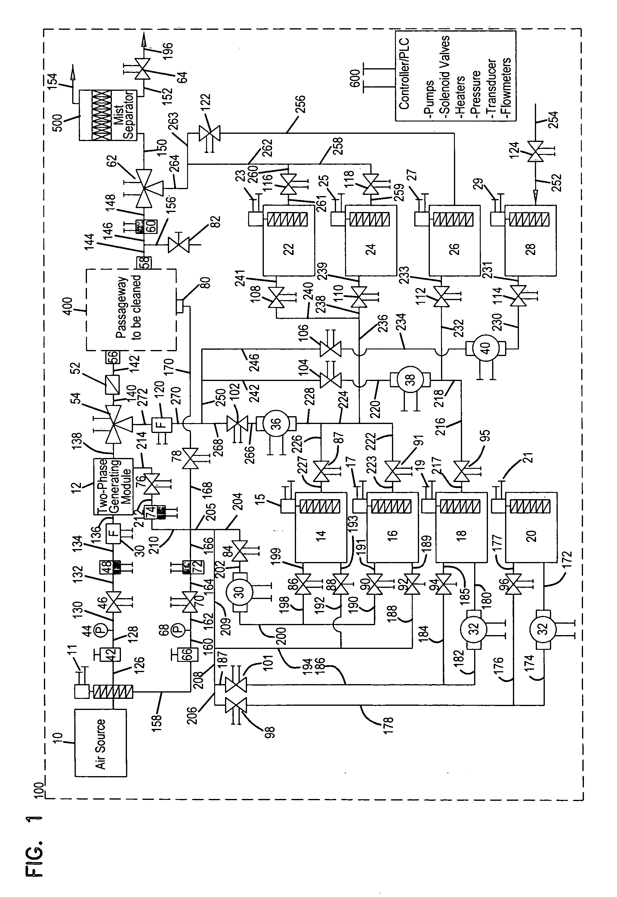
[0107]The tubing was cleaned using the apparatus of FIG. 1 and an alkaline cleaning agent including 0.1% of Tergitol-1X surfactant having a pH of 11.5 for five minutes. The liquid to gas ratio was 1:1800 and the pressure was 45 psig. Air velocities at the inlet and the outlet of the tube were 50 ft / sec and 250 ft / sec, respectively.

[0108]Complete removal of the biofilm from the entire length of the tubing was obtained, as measured by standard microbiology methods. Thus the shear stress of the two-phase flow was high enough to overcome the...

example 3

[0111]This example illustrates the use of apparatus 100 and the two-phase process to remove biofilm and residue from small tubing having an internal diameter between 1.2 to 2 mm and lengths up to 5 meters, with a range of L / D from 2500 to 4000. In this case, the object to be cleaned includes a network of lines as depicted in FIG. 4. This network of lines is referred to as a distribution network in this example and illustrates the use of apparatus 100 in cleaning a network of lines where there is branching and more than one line in the distribution network.

[0112]Referring to FIG. 4, the distribution network has a common inlet line 402, a 3-way valve 404 when the line 402 divides into two lines 406 and 408. Line 408 has a 3-way valve 410, which then splits into two lines 412 and 414. This network of lines became contaminated with biofilm and residues due to the flow of water or like liquids. This kind of arrangement is common in industrial applications such as food and beverage proces...


PUM

PropertyMeasurementUnit
sizeaaaaaaaaaa
velocityaaaaaaaaaa
sizeaaaaaaaaaa

Abstract

An apparatus and method for cleaning passageways and the like with a two-phase mixture of gas under pressure and an aqueous cleaning solution. The two-phase cleaning mixture is generated in a module and is passed out of the module at a predetermined rate that determines droplet size, velocity and droplet density at the pipeline surface to be cleaned. The droplets impact the walls of the passageway to be cleaned, thereby fragmenting, eroding and removing contaminants in said passageway. These are then flushed out of the passageway by the two-phase flow. The flow of cleaning solution can be steady or pulsed. The apparatus and process include a clean-in-place system that is useful in food, beverage, pharmaceutical and similar process industries.

Description

[0001]This invention is a continuation-in-part of Ser. No. 10 / 091,201 filed Mar. 5, 2002, which is a continuation-in-part of Ser. No. 09 / 466,714 filed Dec. 17, 1999, now U.S. Pat. No. 6,454,871 issued Sep. 24, 2002; which is a continuation-in-part of application Ser. No. 08 / 880,062 filed Jun. 23, 1997, now U.S. Pat. No. 6,027,572.[0002]This invention relates to apparatus and method for removing contaminants adhered to a lumen surface. More particularly this invention relates to apparatus and method for cleaning passageways, pipelines, tubing and membranes of adherent contaminants.BACKGROUND OF THE INVENTION[0003]In order to achieve effective cleaning and removal of adhered substances or contaminants, including biofilm, proteins, carbohydrates, lipids, milk residues, deposits of food, beverages, contaminants of pharmaceuticals, including bio-pharmaceuticals and the like from equipment, piping and membrane surfaces, the adhesion forces between such contaminants and the surface to be c...

Claims


Application Information

Patent Timeline
Patent Type & Authority Applications(United States)
IPC IPC(8): B08B9/027B08B3/08A61L2/22A61B19/00A61L2/18A61M1/16B01D65/02B01D65/06B08B9/02C11D3/02C11D3/395C11D3/48C11D11/00C23G1/00C23G5/00G01C5/00G01S13/86G01S13/935G08G5/04
CPCA61B19/34A61M1/1682A61L2/18A61L2/22A61M1/169B01D65/02B01D65/022B01D2321/04B01D2321/185B01D2321/28B08B9/032B08B9/0326B08B9/0327B08B2209/022C11D3/044C11D3/3956C11D3/48C11D11/0041C23G1/00C23G5/00G01C5/005A61B2019/343A61B90/70A61B2090/701B08B9/0328
Inventor LABIB, MOHAMED EMAMLAI, CHUNG-YUETABANI, YACOOB
Owner OLYMPUS CORP
Why Eureka
Try Eureka