Motor Start Circuit with Capacitive Discharge Protection

a technology of capacitive discharge protection and motor start circuit, which is applied in the direction of polyphase induction motor starter, emergency protective circuit arrangement, dynamo-electric converter control, etc., can solve the problems of relay switch chatter, relay switch melt, and motor fuse, and achieve the effect of discharging through the relay winding

Active Publication Date: 2009-09-17
INT CONTROLS & MEASUREMENT
View PDF2 Cites 5 Cited by
  • Summary
  • Abstract
  • Description
  • Claims
  • Application Information

AI Technical Summary

Benefits of technology

[0013]In accordance with one aspect of the present invention, a motor start circuit is provided for an AC induction motor. The motor includes at least one run winding coupled between a pair of AC power conductors and a start winding. The motor start circuit comprises a start capacitor and a normally closed relay switch connected in series with the start winding and with the first and second AC power conductors. The start capacitor and the relay switch define a junction between each other. This motor start circuit employs a DC actuator circuit, in which a DC actuator coil is magnetically coupled to the relay switch; a rectifier arrangement supplies DC power to the DC actuator coil and has AC inputs coupled to the power conductors (e.g., between the two power conductors or between one of them and one end of the start winding). The rectifier arrangement may preferably include a full-wave rectifier diode bridge, but other rectifier arrangements could be used to provide the DC power to the actuator coil. A half full-wave rectifier circuit has one AC input connected to the junction of the start capacitor with the relay switch, and has DC outputs applied across the actuator coil. Then, in the event o

Problems solved by technology

A problem can arise from intermittent application of power to the motor, i.e. to the main AC power conductors.
If the power is switched on and off and back on, power to the relay coil will be intermittent, and this will cause the relay switch to chatter, i.e., to fluctuate between on and off.
This can create a current of several hundred amperes for a short period of time, which must pass through the relay contacts, and can melt them and cause them to fuse.
If the relay contacts are fused closed, the run windings will always have the full

Method used


Image

  • Motor Start Circuit with Capacitive Discharge Protection
  • Motor Start Circuit with Capacitive Discharge Protection
  • Motor Start Circuit with Capacitive Discharge Protection

Examples


Embodiment Construction

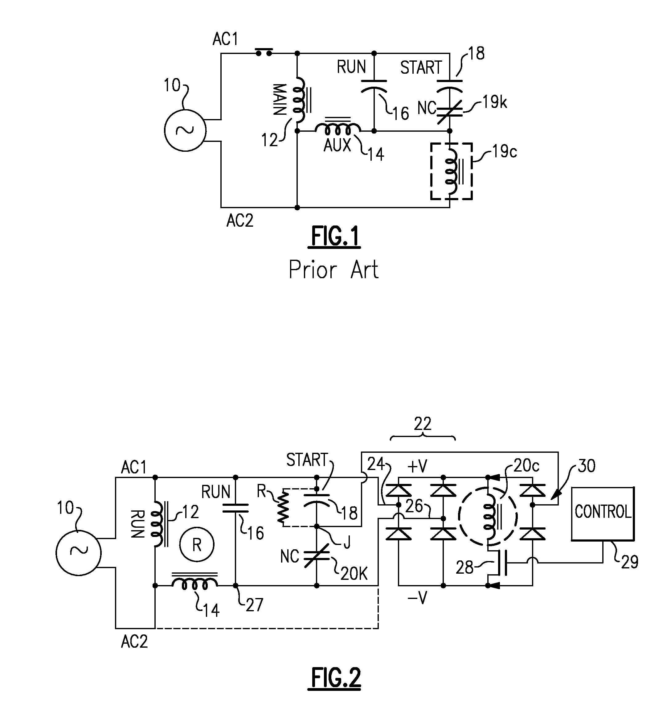
[0021]With reference now to the Drawing, FIG. 1 shows schematically a motor start arrangement according to the prior art. Here, an AC power source 10 supplies single-phase AC power to a pair of AC power conductors AC1 and AC2. A run winding 12 of the motor armature is connected between these AC power conductors. An auxiliary winding or start winding 14 is shown here with a first end connected to one of the AC power conductors AC2 and at a second end coupled through a run capacitor 16 to the other AC winding AC1. A start capacitor 18 is connected in a series with a normally-closed relay switch 19k between the AC power conductor AC1 and the second end of the auxiliary winding or coil 14. An AC relay actuator coil 19c, which is magnetically coupled to the relay switch 19k, is placed with one end at the junction of the start capacitor 18 and the relay switch 19k and with the other end to the second power conductor AC2. A protective thermal switch S is shown in line in AC power conductor...


PUM


Abstract

A motor start circuit for an AC induction motor employs a DC relay whose NC contacts are placed in series with the start capacitor. A half full-wave rectifier arrangement has an AC input connected to the junction of the relay switch and the start capacitor, and DC outputs applied across the relay actuator coil. In the event of intermittent application of power to the motor, any residual charge on the start capacitor will feed current to the actuator coil to hold the relay switch open until the residual charge has decayed sufficiently, to avoid damage to the motor from capacitive discharge. A high magnetic retentivity core can be used to hold the relay off for sufficient time for stored energy to dissipate.

Description

BACKGROUND OF THE INVENTION [0001]The present invention relates to single-phase AC induction motors, and is more particularly concerned with a motor start circuit that controls the flow of AC current to the motor's auxiliary or start winding when the motor is started up.[0002]At start up, AC single-phase induction motors require a starting mechanism to rotate the magnetic field of the field windings, so as to generate sufficient torque to start the rotor. The starting mechanism enables the rotor to overcome the static forces associated with accelerating the rotor and with the load imposed on it. Different motors require different amounts of additional torque at start up. Also, the amount of auxiliary current required depends on initial load conditions, and on the quality of the AC power.[0003]The typical AC induction motor armature is equipped with two sets of windings, namely, one or more main or run windings for driving the motor at a normal operating speed, and an auxiliary or st...

Claims


Application Information

Patent Timeline
IPC IPC(8): H02P1/42H02H7/08
CPCH02P1/021H02P25/04H02P1/445H02P1/44
Inventor KADAH, ANDREW S
Owner INT CONTROLS & MEASUREMENT
Why Eureka
Try Eureka