Multiband antenna device and communication terminal device

a communication terminal and antenna device technology, applied in the direction of elongated active element feed, resonant antennas, antenna earthings, etc., can solve the problems of large radiation efficiency loss, and achieve the effect of reducing the amount of current flowing in the ground plate and restricting the thickness of the antenna devi

Inactive Publication Date: 2009-09-17
SONY MOBILE COMM INC
View PDF5 Cites 64 Cited by
  • Summary
  • Abstract
  • Description
  • Claims
  • Application Information

AI Technical Summary

Benefits of technology

[0007]Since the feed point and the GND point are electrically distant from each other and at least three antenna elements are formed, at least three resonance points are generated, which enables multiple bands. Further, the antenna radiating plate is configured such that an almost entire portion thereof does not face the ground plate, whereby the constraint on the thickness of the antenna device is reduced and the amount of current flowing in the ground plate is reduced.

Problems solved by technology

However, although the use of a parasitic element as disclosed in Japanese Unexamined Utility Model Registration Application Publication No. 62-161410 is suitable for a wider bandwidth, loss in radiation efficiency is large because the parasitic element is connected to the ground plate.

Method used


Image

  • Multiband antenna device and communication terminal device
  • Multiband antenna device and communication terminal device
  • Multiband antenna device and communication terminal device

Examples


Embodiment Construction

[0018]A preferred embodiment of the present invention will be described in detail hereinafter with reference to the drawings.

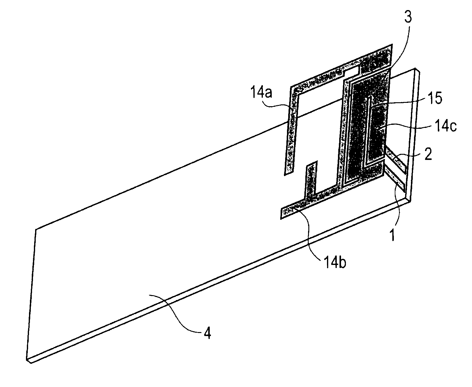
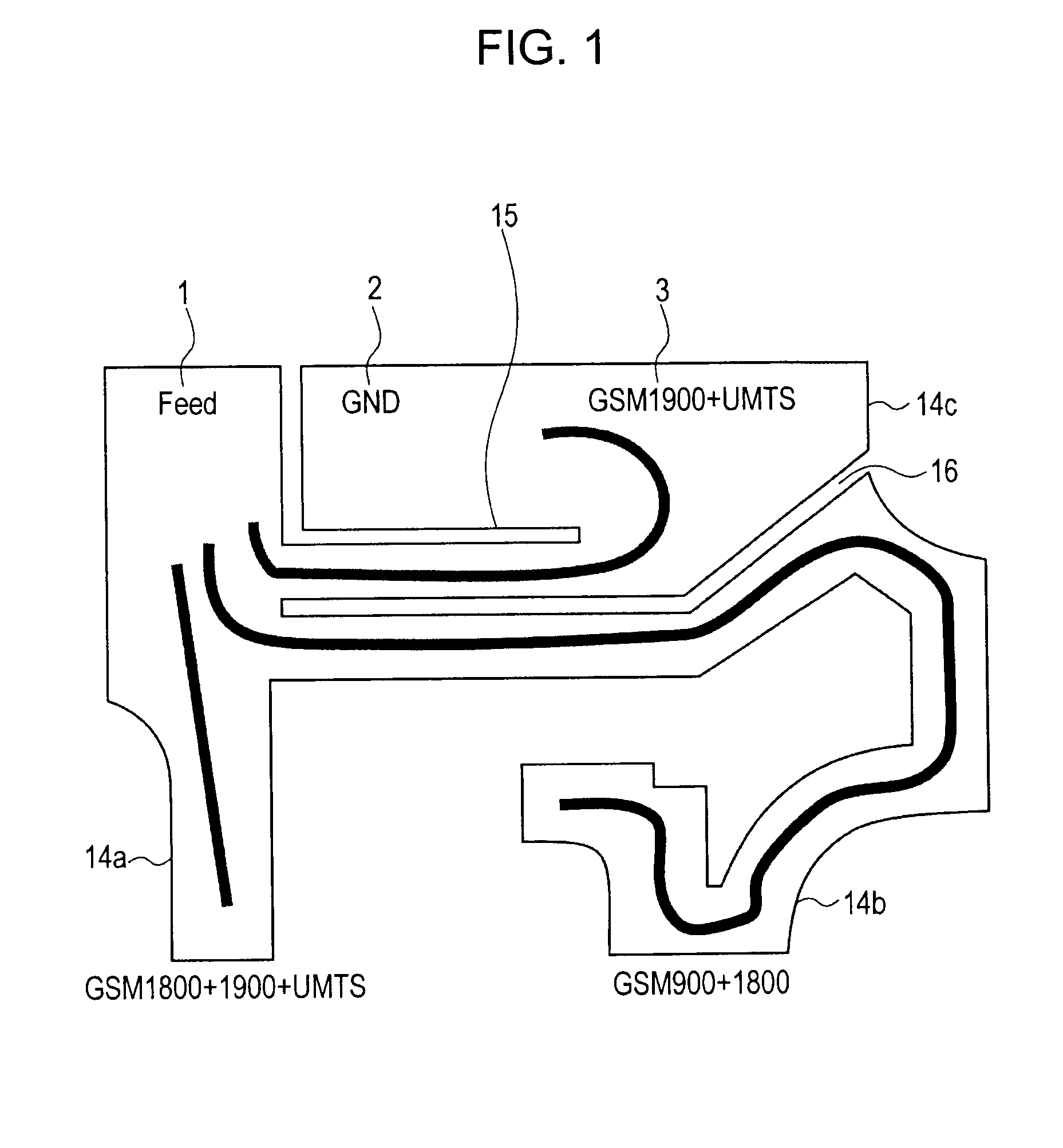
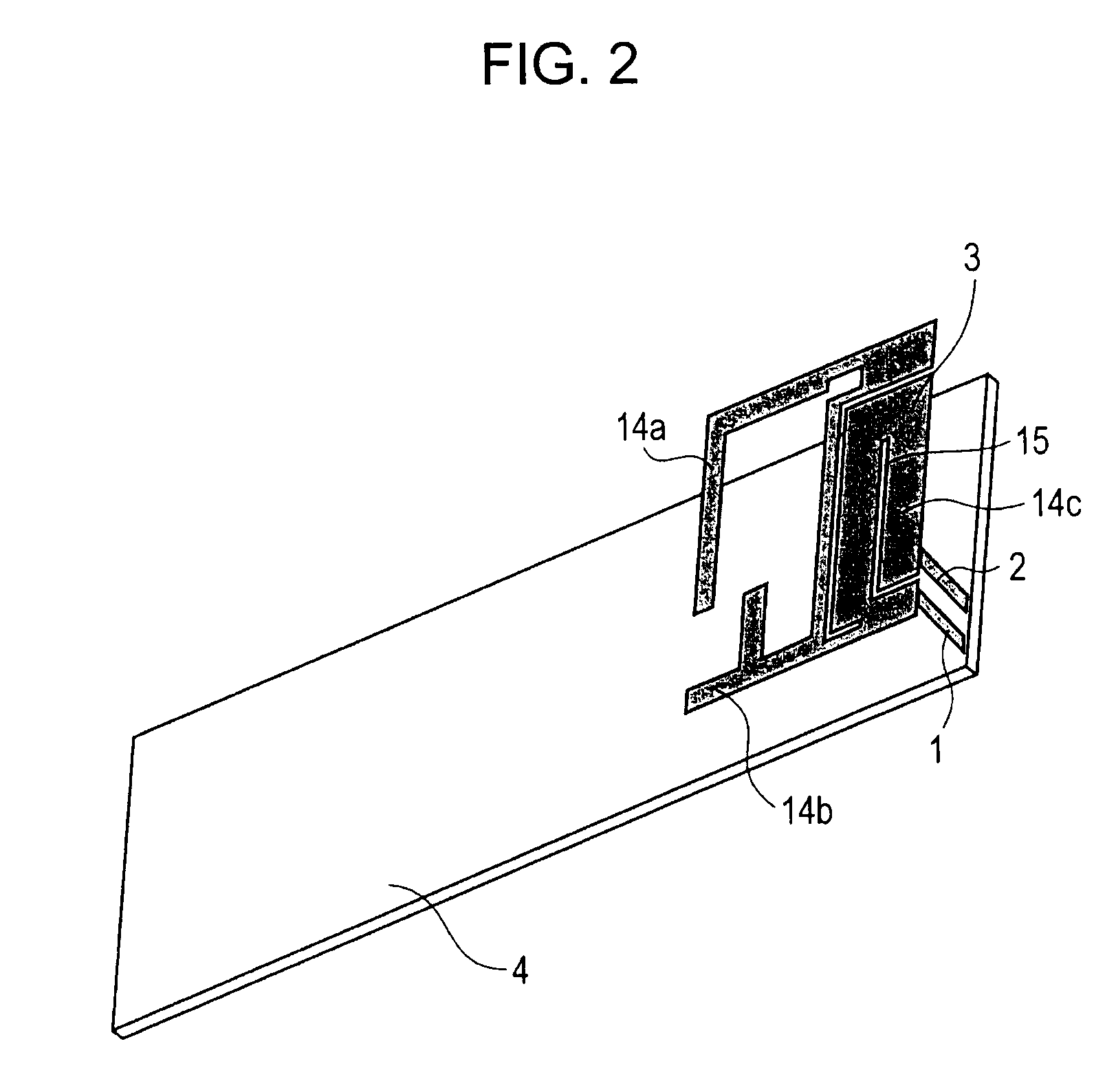
[0019]FIG. 1 shows an example structure of antenna elements in an antenna device according to the embodiment. The antenna device of the present invention is an inverted-F antenna device which uses, together with a GND plate described below, a plate-shaped antenna radiating plate 3 having a feed point 1 and a GND point 2. An antenna structure of the antenna device has a feature of having at least three segmented antenna elements 14a, 14b, and 14c. Thus, the antenna device is provided with a slit 15 formed between the feed point 1 and the GND point 2, and a slit 16 by which the antenna elements 14b and 14c are separated. In particular, the slit 15 serves to make the feed point and the GND point electrically distant from each other. A resonance frequency is adjustable by the length of each antenna element. The antenna elements may be composed of sheet metal or ma...


PUM


Abstract

A slit (15) is formed between a feed point and GND point of an inverted-F antenna to make the points electrically distant from each other, and at least three antenna elements (14a, 14b, and 14c) are formed. The at least three antenna elements (14a, 14b, and 14c) generate at least three resonance points. An antenna radiating plate (3) projects outwardly so that at least a major part thereof does not face a ground plate (4). Therefore, a multi-band antenna device capable of achieving a wider bandwidth without using a parasitic element, and a communication terminal apparatus are provided.

Description

TECHNICAL FIELD[0001]The present invention relates to a multi-band antenna device mounted in a wireless communication terminal such as a portable telephone and supporting multiple bands and to a communication terminal apparatus using the multi-band antenna device.BACKGROUND ART[0002]A planar inverted-F antenna (PIFA) type is mainly used in a multi-band built-in antenna which supports communication in a plurality of frequency bands using a single wireless communication terminal (see Japanese Unexamined Utility Model Registration Application Publication No. 7-14714 and Japanese Unexamined Patent Application Publication No. 2002-344233).[0003]Furthermore, to achieve a wider bandwidth, antennas including a parasitic element connected to a ground (GND) plate have been dominant (see Japanese Unexamined Utility Model Registration Application Publication No. 62-161410).DISCLOSURE OF INVENTION[0004]However, although the use of a parasitic element as disclosed in Japanese Unexamined Utility M...

Claims


Application Information

Patent Timeline
Patent Type & Authority Applications(United States)
IPC IPC(8): H01Q1/38H01Q1/24H01Q1/36H01Q5/10H01Q5/371H01Q9/42H01Q13/08H01Q21/30H04B1/38H04B1/3822
CPCH01Q1/243H01Q1/38H01Q5/371H01Q9/42H01Q21/30H01Q9/0421H01Q1/24H01Q5/10
Inventor ISHIMIYA, KATSUNORI
Owner SONY MOBILE COMM INC
Why Eureka
Try Eureka