Image displaying apparatus and method, and image processing apparatus and method

a technology of image processing and display apparatus, which is applied in the field of image processing apparatus and method, can solve the problems of motion blur, motion blur, and motion blur of liquid crystal display devices

Inactive Publication Date: 2009-09-17
SHARP KK
View PDF9 Cites 44 Cited by
  • Summary
  • Abstract
  • Description
  • Claims
  • Application Information

AI Technical Summary

Benefits of technology

[0070]According to the present invention, different interpolation processes are executed for a plurality of regions having different motion amounts, such as a low-speed region and a high-speed region of an image, to prevent a collapse of an interpolation image from occurring due to a zero-vector preferential interpolation process.
[0071]If an interpolation process other than a motion compensation process is executed for a still region in the low-speed region and a motion compensated interpolation process is executed in accordance with motion vectors for a still region in the high-speed region, the low-speed region is expanded by a predetermined amount to alleviate a collapse occurring at the ends of the low-speed region due to motion of the high-speed region image.

Problems solved by technology

As compared to conventional cathode-ray tubes (CRTs) primarily used for realizing moving images, LCDs (Liquid Crystal Displays) have a drawback, so-called motion blur, which is, blurring of outline of a motion portion perceived by a viewer when displaying an image with motion.
Since impulse response of image displaying light has a temporal spread in the above hold display mode, temporal frequency characteristics are deteriorated along with spatial frequency characteristics, resulting in the motion blur.
That is, since the human eyes can smoothly follow a moving object, if the light emission time is long as in the case of the hold type, motion of image seems jerky and unnatural due to a time integration effect.
However, in the case of the frame interpolation using linear interpolation between frames, unnaturalness of motion (jerkiness, judder) is generated due to the frame rate conversion, and the motion blur disturbance due to the above hold display mode cannot sufficiently be improved, resulting in inadequate image quality.
If a peripheral image of the still region moves (scrolls) at a high speed, this causes the collapse since a motion amount of object during one frame period becomes large.
In FIG. 28, if an interpolation process is executed with the use of the motion vector (arrow shown by a dot line), it is problematic that the collapse such as those formed by pulling the low-speed region image occurs due to the effect of the low-speed region image in a region shown by I of the interpolation frame where the high-speed region image should normally exist.

Method used


Image

  • Image displaying apparatus and method, and image processing apparatus and method
  • Image displaying apparatus and method, and image processing apparatus and method
  • Image displaying apparatus and method, and image processing apparatus and method

Examples


first embodiment

[0160]In a first embodiment of the present invention, an input image is separated into the low-speed region and the high-speed region, and the motion compensation process in the FRC portion 10 is disabled by setting zero-vector for the interpolation vector of the interpolation block corresponding to the still region in the low-speed region so as to execute the zero-vector preferential interpolation process for the still region in the low-speed region and not to execute the zero-vector interpolation process for the still region in the high-speed region.

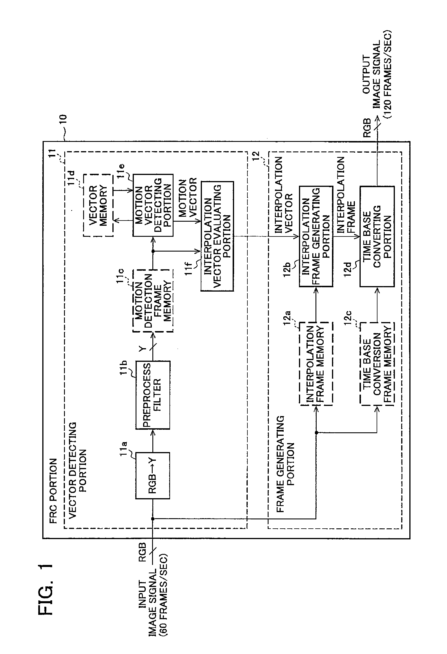
[0161]FIG. 5 is a block diagram of a main configuration example of the interpolation frame generating process according to the first embodiment of the present invention. The configuration of the present embodiment includes the delaying portion 111e, a low-speed region detecting portion 112e, a still-region detecting portion 113e, the interpolation vector controlling portion 114e, the first interpolation frame generation processing port...

second embodiment

[0176]In a second embodiment of the present invention, an input image is separated into the low-speed region and the high-speed region, and the motion compensation process in the FRC portion 10 is disabled by setting zero-vector for the interpolation vector of the interpolation block of the interpolation frame generating portion 12b corresponding to the still region in the low-speed region so as to execute the zero-vector preferential interpolation process for the still region in the low-speed region and not to execute the zero-vector interpolation process for the still region in the high-speed region.

[0177]FIG. 8 is a block diagram of a main configuration example of a liquid crystal displaying apparatus according to the second embodiment of the present invention and the liquid crystal displaying apparatus includes the FRC portion 10, the controlling portion 13, the electrode driving portion 14, and the liquid crystal displaying panel 15. The FRC portion 10 includes the motion vecto...

third embodiment

[0184]In a third embodiment of the present invention, a linear interpolation processing portion is included on a path different from the input path to the FRC portion 10; an input image is separated into the low-speed region and the high-speed region; and the image signals from the linear interpolation are interpolated into the still region in the low-speed region so as to execute the linear interpolation process for the still region in the low-speed region and to execute the motion compensated interpolation process for the still region in the high-speed region. That is, the process is switched such that the frame rate conversion is performed by executing the linear interpolation process without executing the motion compensated interpolation process for a pixel corresponding to the still region in the low-speed region or a region including the pixel.

[0185]FIG. 9 is a block diagram of a main configuration example of a liquid crystal displaying apparatus according to the third embodim...


PUM


Abstract

In an image displaying apparatus including a motion compensated rate converting (FRC) portion, deterioration of image quality is prevented in an image having a high-speed region and a low-speed region mixed. The FRC portion includes a motion vector detecting portion 11e and an interpolation frame generating portion 12b. The motion vector detecting portion 11e includes a first region detecting means 112e1 that detects a first region (high-speed region) including a motion amount equal to or greater than a first predetermined amount from an input image signal, a second region detecting means 112e2 that detects a second region (low-speed region) including a motion amount equal to or less than a second predetermined amount from the input image signal, and a third region detecting means 113e that detects a still region from an inter-frame difference of the input image signal. The interpolation frame generating portion 12b executes a motion compensated interpolation process using motion vectors for the still region in the first region (background) and executes a zero-vector interpolation process for the still region in the second region (foreground).

Description

TECHNICAL FIELD[0001]The present invention relates to an image displaying apparatus and method and an image processing apparatus and method that include a function of converting a frame rate or field rate and, more particularly, to an image displaying apparatus and an image displaying method of the apparatus and an image processing apparatus and an image processing method of the apparatus that can execute different interpolation processes for a plurality of regions having different vector amounts, such as foreground and background of an image, when executing a motion compensated rate conversion process.BACKGROUND OF THE INVENTION[0002]As compared to conventional cathode-ray tubes (CRTs) primarily used for realizing moving images, LCDs (Liquid Crystal Displays) have a drawback, so-called motion blur, which is, blurring of outline of a motion portion perceived by a viewer when displaying an image with motion. It is suggested that this motion blur arises from the LCD display mode itsel...

Claims


Application Information

Patent Timeline
Patent Type & Authority Applications(United States)
IPC IPC(8): G09G5/00G09G3/34
CPCG09G3/2096G09G3/3648G09G2320/0261G09G2320/106H04N7/014G09G2340/16H04N5/144H04N7/013G09G2340/14
Inventor HANAOKA, TOSHIHARUYOSHIDA, YASUHIROUENO, MASAFUMIFURUKAWA, HIROYUKIYAMAMOTO, KENICHIROHYOSHII, TAKASHI
Owner SHARP KK
Why Eureka
Try Eureka