Hybrid Telecom Network-structured Architecture and System for Digital Image Distribution, Display and Projection

Active Publication Date: 2009-09-17
PHOTONICA
View PDF8 Cites 17 Cited by
  • Summary
  • Abstract
  • Description
  • Claims
  • Application Information

AI Technical Summary

Benefits of technology

[0019]The present invention contemplates a division of labor approach, as different materials and structures, whether implemented for image display or photonic integrated circuits, do exhibit different relative strengths and advantages. At

Problems solved by technology

A degree of hybridization in some display technology solutions does exist now, at the time of the present disclosure, but to a limited

Method used


Image

  • Hybrid Telecom Network-structured Architecture and System for Digital Image Distribution, Display and Projection
  • Hybrid Telecom Network-structured Architecture and System for Digital Image Distribution, Display and Projection
  • Hybrid Telecom Network-structured Architecture and System for Digital Image Distribution, Display and Projection

Examples


case 1 embodiment

SUB-CASE 1 EMBODIMENT

Multiple Image Devices Driving Sectorized Display

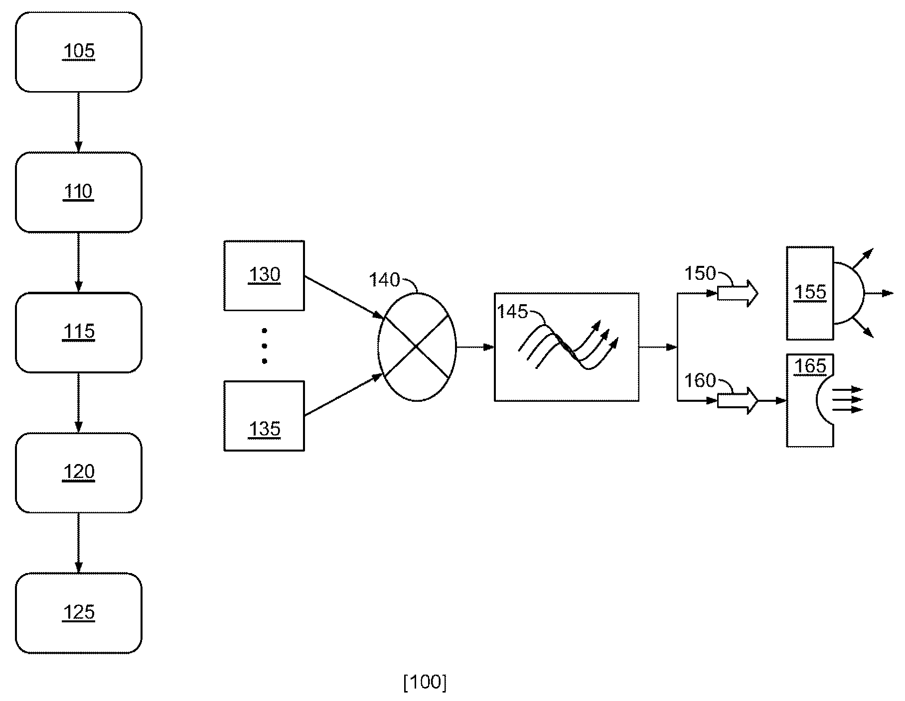
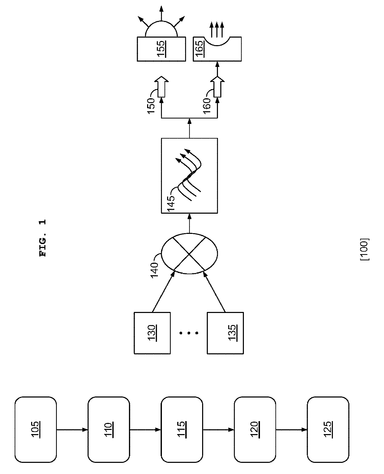
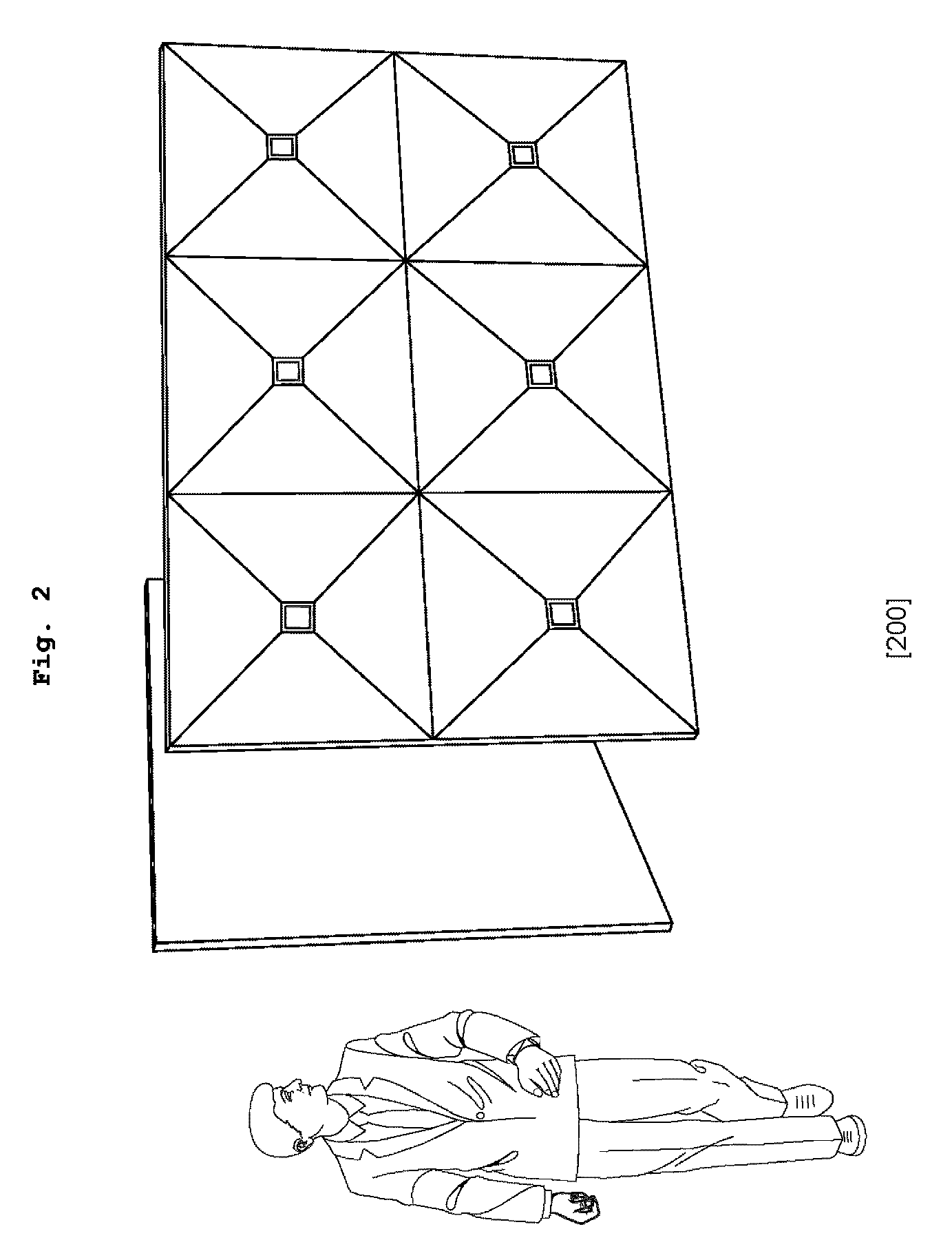
[0107]A typical version of this embodiment would find a large flat panel display, fabricated in the same Jacquard-loom fiberoptic textile-matrix method disclosed above. But it would differ from the simplest case in the prior embodiment in that instead of all the addressing optical fibers loomed and gathered in a “fan-out” from one (simplest case: central) smaller image generating device, forming in perspective a small, very flat pyramidal structure, would be gathered by the display sector (a subsection of the overall viewable display surface) into multiple pyramidal structures, edge-to-edge adjacent 200.

[0108]A 4:3 landscape flat panel display, then, might have 6 smaller (for instance, cell-phone type) displays, three for the top half, three for the bottom half, dividing the overall display into 6 sectors. In this example, the cell-phone type displays would be back-illuminated by a more powerful source then used i...

case 2 embodiment

SUB-CASE 2 EMBODIMENT

Multiple Image Devices to Drive Duplicate Pixels in Larger Viewable Displays

[0115]In very large direct-view displays, as the ratio of the area of the viewable display surface and the size of the image generating device increases in magnitude, an auxiliary method for addressing the problem of upscaling pixels is to employ duplicate image generating devices via 300 to drive duplicate pixels, forming “meta-pixels” in large scale displays composed of multiple optical fibers or meta-fibers as shown in 500.

[0116]Thus, a relatively smaller image-generating device that is a driver of a larger-area display may have greater native resolution than the larger viewable display and use that native resolution to drive duplicate pixels (pixels in groups with the same image information or on-off state). i.e., a 4k compact image generating device driving an HD or 2k viewable display has 4×HD of pixel capacity. Those extra pixels would simply send the same pixel information down 4...


PUM


Abstract

A hybrid and telecom-structured image display and projection system implementing a desired image display and projection solution that is fast, cheap to manufacture, low-power, light-weight, scalable in size and resolution, fast-switching and capable of a broad range of mode characteristics of light for implementing dimensional display and projection, flexible, rigid-flat, or rigid-conformal as needed.

Description

BACKGROUND OF THE INVENTION[0001]The present invention relates generally to displays and projectors and more specifically to an image display and projection technology that transcends limitations of mono-technologies and use the strengths of best-in-breed methods for each desired image display and projection characteristic.[0002]In the field of image display and projection technologies limitations have been revealed in all existing mono-technologies which prevent them from implementing the next generation of hi-speed, low cost, low power, flexible, wearable, and dimensional display forms.[0003]A shared limitation arises from the general reliance on a single pixel-switching component technology to implement the entire image-generation architecture, as typically any one pixel-switching component technology, whether a liquid crystal (LC) cell or gas plasma cell, a digital micro-mirror device (DMD), a magneto-optic (MO) switch, or an organic light emitting diode (OLED), excels in one or...

Claims


Application Information

Patent Timeline
IPC IPC(8): G09G5/00H04N9/31
CPCH04N9/3147G03B21/00G03B21/005
Inventor ELLWOOD,, JR., SUTHERLAND C.
Owner PHOTONICA
Why Eureka
Try Eureka