Inkjet head, method of detecting ejection abnormality of the inkjet head, and method of forming film

a technology of inkjet head and inkjet head, which is applied in the direction of typewriters, printing, power drive mechanisms, etc., can solve the problems of reducing the operating rate of the apparatus, reducing the use of orientation film material, and increasing the amount of inkjet head, so as to reduce the pitch of the nozzle, the effect of reducing the nozzle and performing with eas

Active Publication Date: 2009-09-17
ISHII HYOKI
View PDF4 Cites 27 Cited by
  • Summary
  • Abstract
  • Description
  • Claims
  • Application Information

AI Technical Summary

Benefits of technology

[0068]In the inkjet head according to the present invention which is accomplished to attain the first technical object, there are provided n number of line-type inkjet nozzles which include nozzles that eject a liquid material and are arranged in a row, and which are arranged in parallel with each other such that positions of the nozzles are shifted from each other by 1/n of a nozzle pitch. As a result, in the inkjet head as a whole, the nozzle pitch can be made narrower than the physical limit to reduce the nozzle pitch. In addition, since the line-type inkjet nozzles are combined with each other, by adjusting an ejection timing of each of the line-type inkjet nozzles, the dot pitch can be adjusted and adjustment such as fine coating and rough coating can be performed with ease. Further, in the position adjustment method for the line-type inkjet nozzles according to the present invention, the position of each of the line-type inkjet nozzles is adjusted to a position at which each of the line-type inkjet nozzles is to be mounted, based on an image of each of the line-type inkjet nozzles arranged in parallel with each other, which is picked up by a camera. Accordingly, the positions of the line-type inkjet nozzles can be adjusted with precision. Further, in the position adjustment method for the inkjet nozzle units according to the present invention, by using a mounting shaft having a reference plane being a reference for a mounting position of each of the inkjet nozzle units, the inkjet nozzle units are positioned to mount on the reference plane of the mounting shaft. The reference plain surface of the mounting shaft is one plane surface, and the straightness and the flatness thereof can be relatively easily secured. For this reason, the precision of the reference surface to which the inkjet nozzles units are mounted can be relatively easily secured, thereby making it possible to perform positioning of the inkjet nozzle units with precision to mount thereon. In those inkjet heads, the nozzle pitch can be made narrower, and adjustment of the dot pitch can be performed with ease, so the inkjet heads are suitable as, for example, inkjet print heads for an orientation film forming device.
[0069]In the method of detecting ejection abnormality of the inkjet head according to the present invention which is accomplished to attain the above-mentioned second technical object, based on taken images of a liquid material ejected from a nozzle of the inkjet head, at least two positions in an ejecting direction of the nozzle, a position or a liquid width of the liquid material is calculated to detect ejection abnormality of the nozzle. In a case where there occurs an ejection abnormality in the nozzle, a remarkable difference is obtained in amount of characteristic of the position or the liquid width of the liquid material. Thus, the ejection abnormality of the nozzle can be detected with ease and reliability. Further, a light source is disposed so as to be opposed to the camera on an opposite side of the camera with respect to the liquid material ejected from the nozzle so that direct light projected from the light source does not enter a finder of the camera, and reflected light obtained by reflecting the direct light, which is projected from the light source, by the liquid material ejected from the nozzles, is captured by the camera. As a result, when the liquid material ejected from the nozzles, is ph

Problems solved by technology

That is: for example, (1) a failure that the orientation film material is not coated on the transparent substrate repeatedly occurs in a case where dust is attached to a surface of a relief printing plate; (2) usage of the orientation film material is large in amount; (3) a recovery time becomes longer and operating ra

Method used


Image

  • Inkjet head, method of detecting ejection abnormality of the inkjet head, and method of forming film
  • Inkjet head, method of detecting ejection abnormality of the inkjet head, and method of forming film
  • Inkjet head, method of detecting ejection abnormality of the inkjet head, and method of forming film

Examples


first embodiment

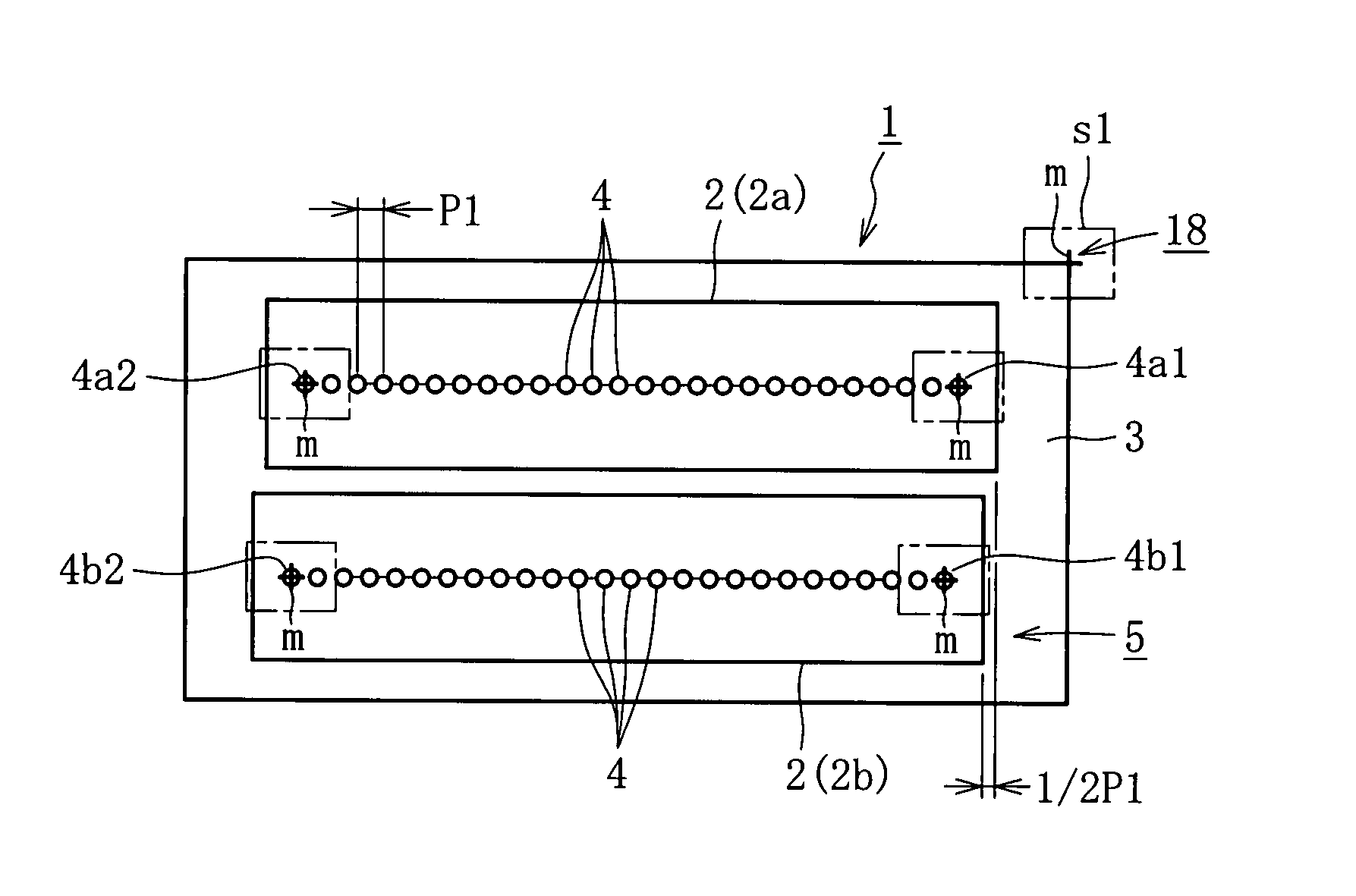
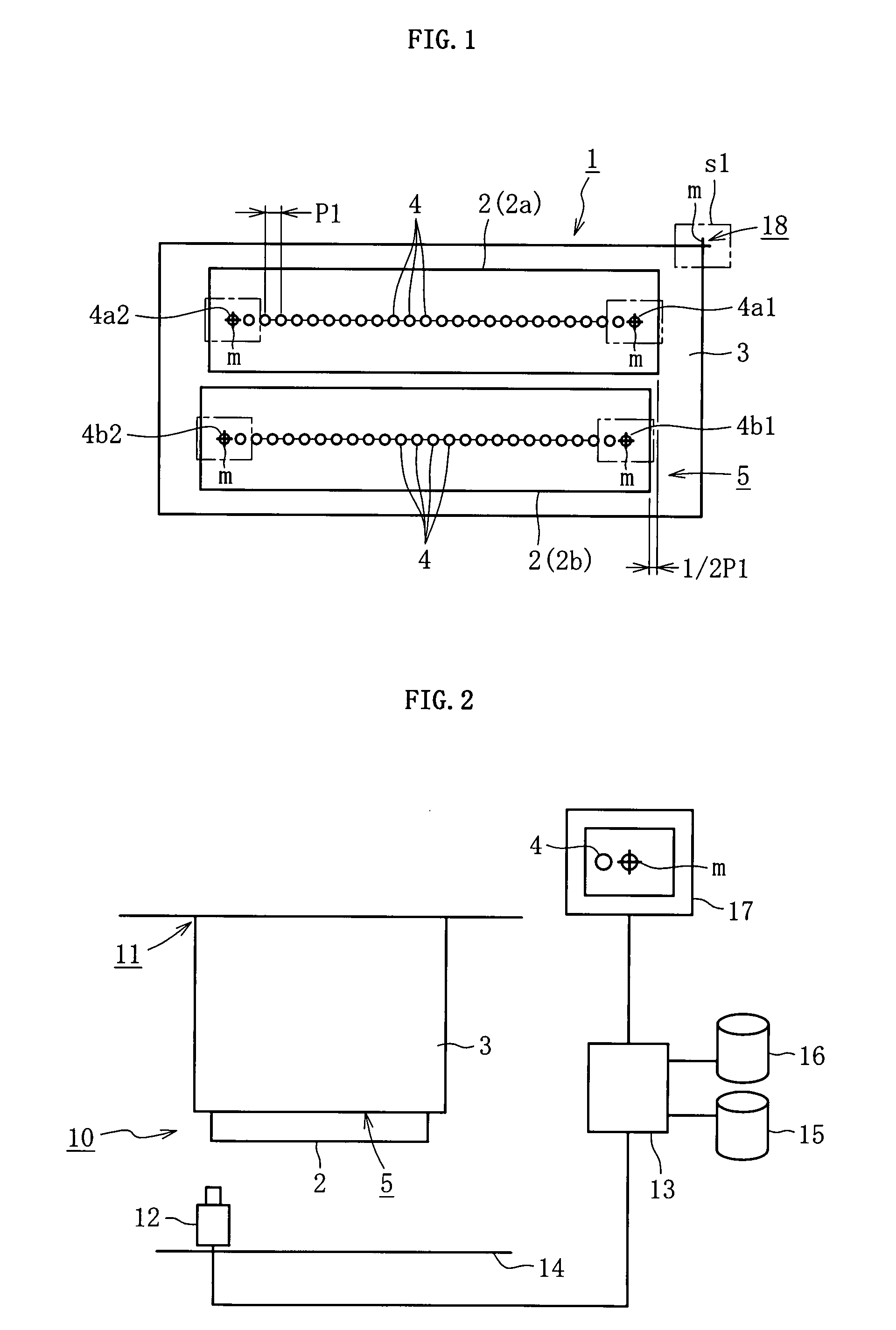
[0137]FIGS. 1 to 6 each illustrate a first embodiment of the present invention. As illustrated in FIG. 1, an inkjet head 1 according to the first embodiment includes two line-type inkjet nozzles 2a and 2b, and a housing 3 to which the line-type inkjet nozzles 2a and 2b are mounted.

[0138]The line-type inkjet nozzles 2a and 2b each include nozzles 4 that eject a liquid material and are arranged in a row at predetermined intervals. The nozzles 4 are formed at the same time when the line-type inkjet nozzles 2a and 2b are formed, thereby making it possible to produce the nozzles 4 with high precision in their shapes and positions. The line-type inkjet nozzles 2a and 2b each have a structure in which the liquid material is supplied to each of the nozzles 4 from a liquid material supplying portion (not shown), and the liquid material is ejected at a predetermined timing in response to an injection command signal sent by a controller (not shown). As a result, the line-type inkjet nozzles 2a...

second embodiment

[0189]FIG. 7 toll each illustrate a second embodiment of the present invention. As illustrated in FIGS. 7 and 8(a), an ejection abnormality detecting device 1 for an inkjet head according to the second embodiment includes a camera 5 for photographing a liquid material 4 ejected from nozzles 3 of an the inkjet head 2, a light source 6 for illuminating light necessary for photographing, and an ejection abnormality detecting portion 7 for processing an image taken by the camera 5 to detect an ejection abnormality. Note that, in this embodiment, as illustrated in FIG. 7, the inkjet head 2 has a structure in which identical inkjet heads 2a including the nozzles 3 that are arranged in series such that positions thereof are alternately shifted from each other in the longitudinal direction in a staggered manner.

[0190]As illustrated in FIG. 7, the camera 5 is disposed so as to be capable of photographing the liquid material 4 (see FIG. 8(a)) ejected from the inkjet head 2, from the direction...

third embodiment

[0216]FIGS. 13 to 17 each illustrate a third embodiment of the present invention. As illustrated in FIG. 13, a film forming device 1 according to the third embodiment includes an inkjet head 10, a film thickness setting portion 20, a film thickness data storage portion 30, a gray level distribution chart creating portion 40, and a film forming portion 50.

[0217]In this embodiment, in an inkjet nozzle unit 13, line-type inkjet nozzles 12 each including nozzles 11 that eject the liquid material and are arranged in a row are provided in parallel with each other such that the positions of the nozzles 11 are shifted from each other by a half of a nozzle pitch Pn, that is, ½Pn. In the inkjet head 10, the inkjet nozzle units 13 are provided in series by alternately shifting the positions of the nozzles 11 of each of the line-type inkjet nozzles 12 in the direction in which the nozzles 11 are provided in a staggered manner.

[0218]In the inkjet head 10, the line-type inkjet nozzles 12 each inc...


PUM


Abstract

There are provided n number of line-type inkjet nozzles (2) which include nozzles (4) that eject a liquid material and a rearranged in a row, and which are arranged in parallel with each other so that positions of the nozzles (4) are shifted from each other by 1/n of a nozzle pitch (P1). Thus, an inkjet head (1) as a whole has a state equivalent to a state in which the nozzles (4) are arranged at 1/n of a nozzle pitch of one line-type inkjet nozzle (2). The inkjet head (1) is capable of adjusting a timing of ejecting the liquid material for each line-type inkjet nozzle (2). Accordingly, adjustment of a dot pitch such as fine coating and rough coating can be performed with ease.

Description

TECHNICAL FIELD[0001]The present invention relates to an inkjet head, a method and a device for detecting an ejection abnormality of the inkjet head, and a method (film coating method) and a device for forming a film by using the inkjet head.BACKGROUND ART[0002]In recent years, a so-called inkjet method using an inkjet head has been widely employed in a case of performing printing using ink on a print medium such as paper, in a case of forming an orientation film or applying UV ink onto a substrate (transparent substrate) of a liquid crystal display device or the like, or in a case of applying a color filter onto a substrate of an organic EL display device.[0003]For example, JP 3073493 B discloses an inkjet head including line-type inkjet nozzles in which nozzles are arranged in a row. JP 3073493 B also discloses a technology of improving a process speed for coating a liquid material by devising arrangement of the line-type inkjet nozzles as shown in FIGS. 5 to 7 of JP 3073493 B (Pa...

Claims


Application Information

Patent Timeline
IPC IPC(8): B41J25/308B41J2/155B41J29/38B41J2/205B41J2/175
CPCB41J2/145B41J2/175B41J29/393B41J2/2146B41J2/18B41J2/01B41J2/135B41J25/308
Inventor NAKANO, TERUYUKIKOZAWA, YASUHIRO
Owner ISHII HYOKI
Why Eureka
Try Eureka