Fiber optic multiplexer

a fiber optic multiplexer and fiber optic technology, applied in the field of fiber optic multiplexers, can solve the problems of reducing the beam intensity, increasing the noise level, and reducing the signal strength, and achieving the effect of reducing the beam intensity, and reducing the beam transmission ra

Inactive Publication Date: 2009-09-17
ECI TECH INC
View PDF9 Cites 63 Cited by
  • Summary
  • Abstract
  • Description
  • Claims
  • Application Information

AI Technical Summary

Benefits of technology

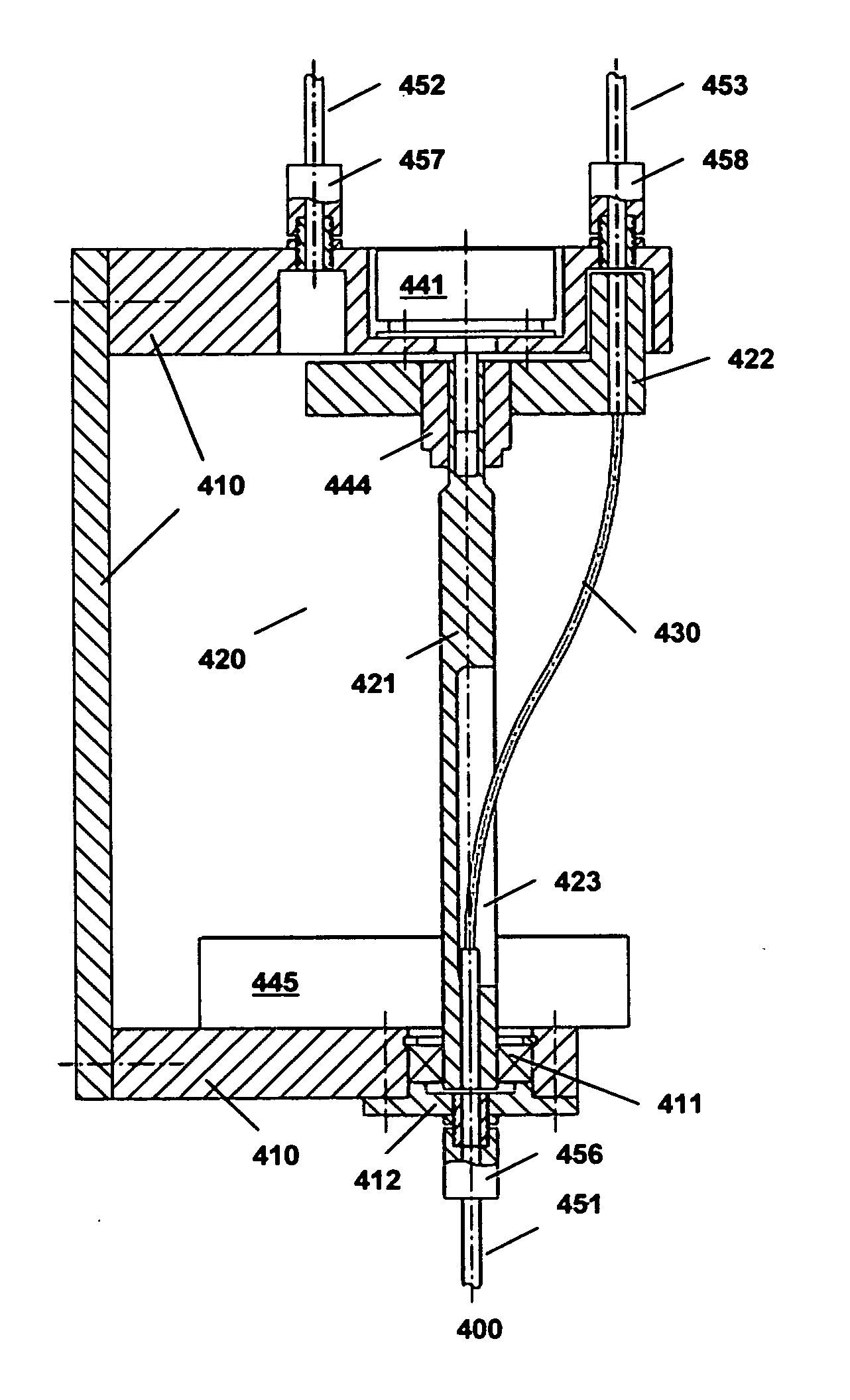
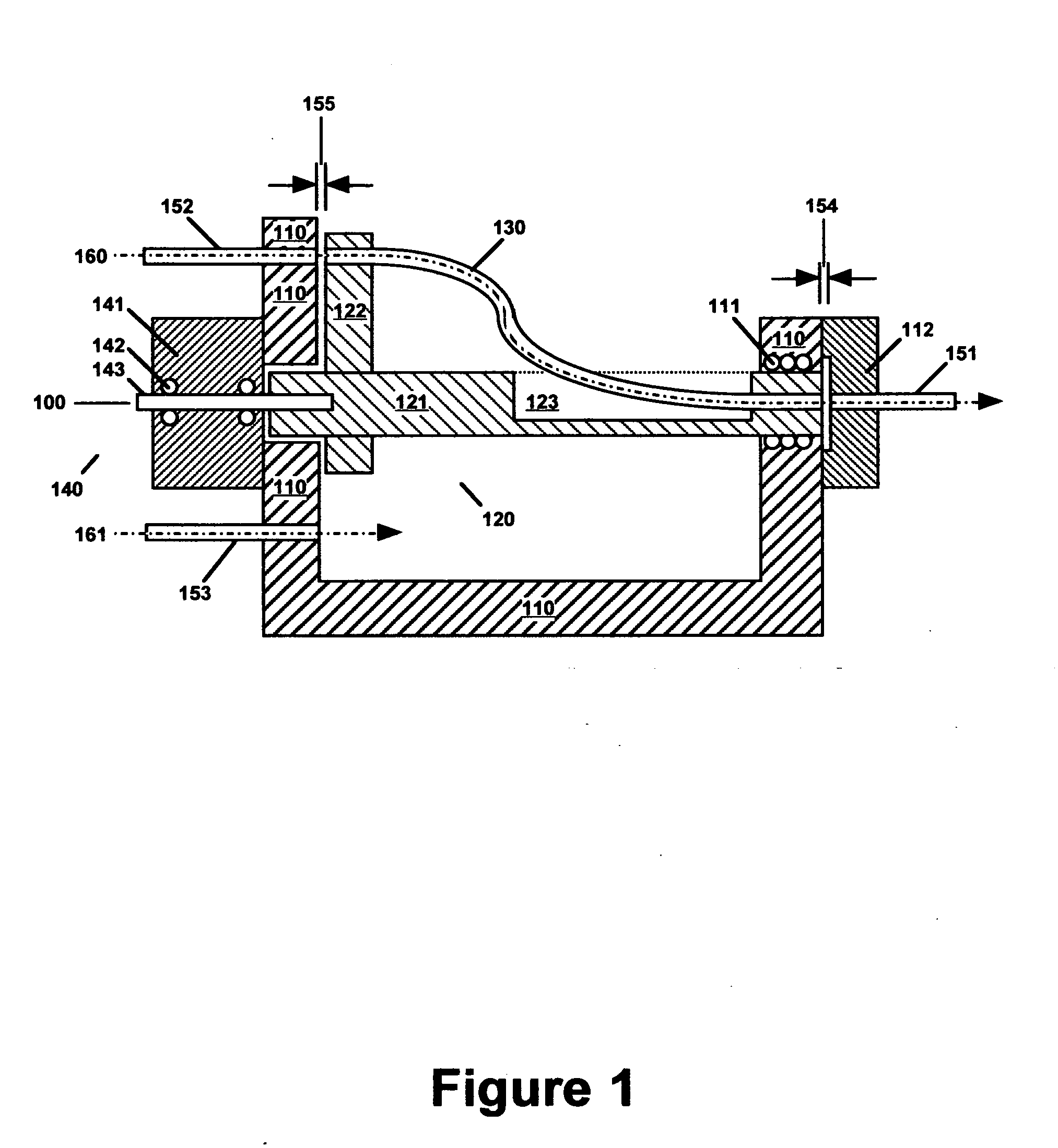
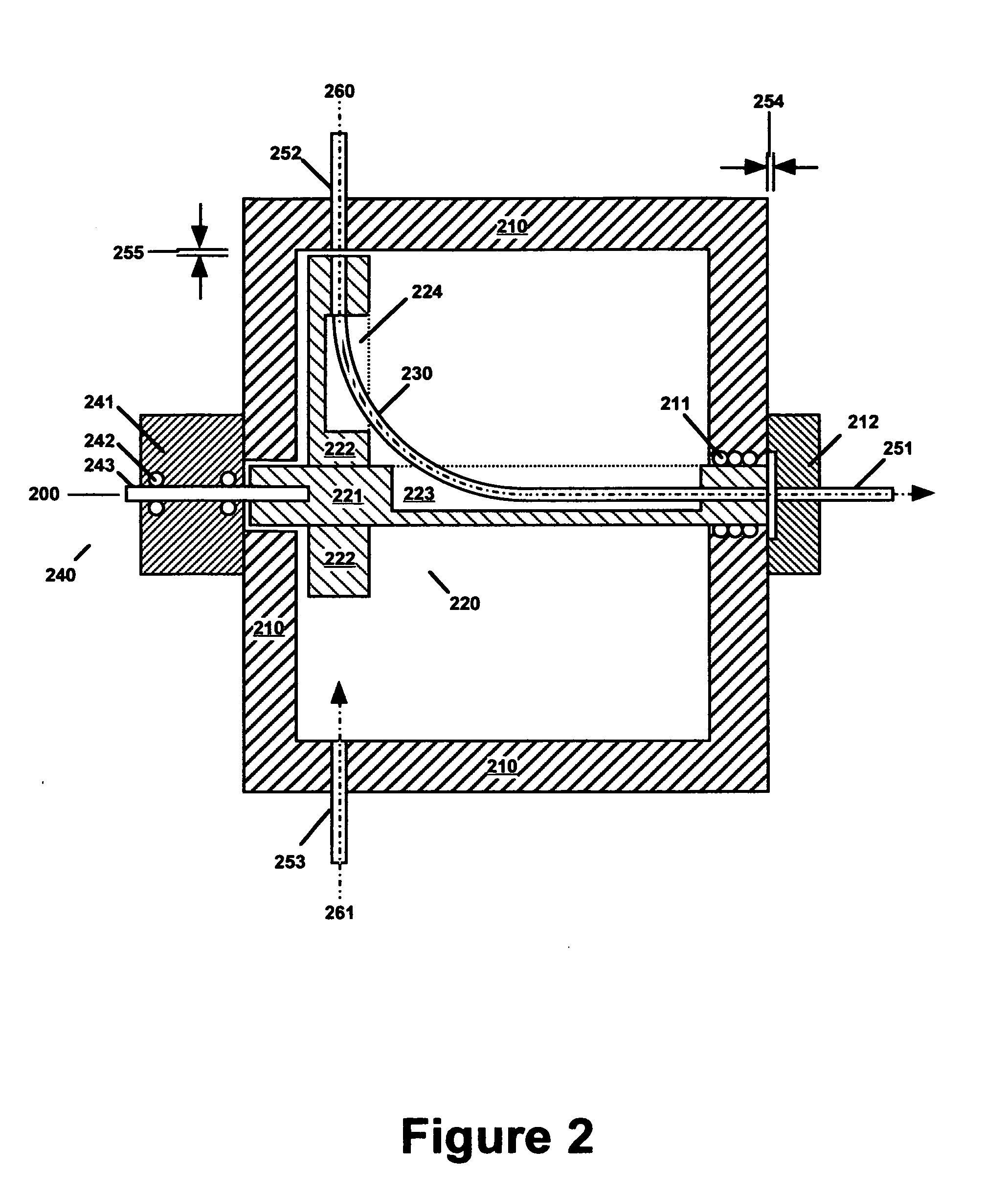
[0013]The invention provides a fiber optic multiplexer device and a method for selectively transferring electromagnetic radiation between a primary optical fiber and a plurality of secondary optical fibers without twisting or otherwise stressing the optical fibers. This is accomplished by interposing a mobile optical fiber between the primary optical fiber and the secondary optical fibers, which are stationary.
[0020]The invention provides a fiber optic multiplexer that exhibits high efficiency for beam transmittance and low noise since distortion and stress of the optical fibers are avoided, and the distance that the beam traverses in air is small. The device is particularly useful for on-line analysis and control of a plurality of industrial processing solutions using the same spectroscopic analysis instrumentation.

Problems solved by technology

Since the input fibers are stationary and have a finite diameter, the beams in this case must impinge the end of the receiving fiber at a substantial angle (relative to the axis of the receiving fiber) and / or from a substantial distance, which greatly increases the noise level and decreases the signal strength.
In this case, multiple reflections inside the averaging sphere provide coaxial beams to the receiving fiber but also greatly decrease the beam intensity.
This approach typically provides less than 0.1% beam transmission, resulting in low signal-to-noise ratio.
One disadvantage of this approach is that the input beams must traverse a relatively large distance through the atmosphere between the input optical fibers and the receiving optical fiber.
In this case, moisture and contaminants in the atmosphere may interfere with spectroscopic analyses, especially those involving near infrared (NIR) radiation at wavelengths strongly absorbed by water.
Mirrors also tend to tarnish and collect dust from the atmosphere, which can significantly degrade the signal-to-noise ratio.
Enclosing the multiplexer in a vacuum chamber can mitigate these disadvantages but is inconvenient and significantly increases equipment and operating costs.
A major disadvantage of this prior art approach is that rotation of the wheel twists and stresses optical fibers attached to the wheel, which causes erratic results and introduces significant noise.

Method used


Image

  • Fiber optic multiplexer
  • Fiber optic multiplexer
  • Fiber optic multiplexer

Examples


Embodiment Construction

[0026]Terminology used in this document is generally known to those skilled in the art. The term “optical fiber” encompasses a single optical fiber as well as a bundle of optical fibers used together as a fiber optic element or probe. A preferred optical fiber for use with the invention has a single optical fiber core. Optical fibers generally have a circular cross-section and flat ends perpendicular to the optical fiber axis. In some cases, an optical fiber may comprise an optical window on one or both ends. Optical fibers may comprise a variety of optically transparent materials depending on the wavelength region involved. As applied to optical fibers, the term “end” generally denotes the end section of an optical fiber that is used for attachment but may also encompass the flat end of the optical fiber when the meaning is unambiguous. In this document, the term “geometric end” is sometimes used to distinguish the flat end of the optical fiber to avoid ambiguity. It is understood,...


PUM


Abstract

A fiber optic multiplexer comprises a stationary frame to which primary and secondary optical fibers are attached, a rotary frame to which both ends of a transfer optical fiber are attached, and a means of rotating the rotary frame through a predetermined angle relative to the stationary frame. The primary end of the transfer optical fiber is coaxial with the primary optical fiber and the rotary frame axis of rotation. The secondary end of the transfer optical fiber is initially coaxial with a first secondary optical fiber. The multiplexer is switched by rotating the rotary frame through the predetermined angle to coaxially align the secondary end of the transfer optical fiber with a second secondary optical fiber.

Description

CROSS-REFERENCE TO RELATED APPLICATIONS[0001]The present nonprovisional application claims priority to U.S. Provisional Application No. 61 / 069,448 entitled “Fiber Optic Multiplexer” to Barmash et al. (filed on 14 Mar. 2008) and to U.S. Provisional Application No. 61 / 131,593 entitled “Improved Fiber Optic Multiplexer” to Barmash et al. (filed on 9 Jun. 2008), which all have the same inventors and the same assignee.BACKGROUND OF THE INVENTION[0002]1. Field of the Invention[0003]This invention is concerned with fiber optic systems, and particularly with switching electromagnetic radiation between optical fibers.[0004]2. Description of the Related Art[0005]Fiber optic systems are widely used to convey electromagnetic radiation from one location to another location in order to control industrial processes. For example, an optical fiber may be used to convey a measurement beam from a source of electromagnetic radiation to an analysis cell containing a sample of a processing solution to be...

Claims


Application Information

Patent Timeline
Patent Type & Authority Applications(United States)
IPC IPC(8): G02B6/26
CPCG02B6/3504G02B6/3558G02B6/355
Inventor BARMASH, SUNYAKAVALERCHIK, BORISLIANG, GUANGSHALYT, EUGENEBRATIN, PETER
Owner ECI TECH INC
Why Eureka
Try Eureka