Method and device for controlling the oil supply of an automatic gearbox and a starting element

a technology of automatic transmission and starting element, which is applied in the direction of positive displacement liquid engine, piston pump, machine/engine, etc., can solve the problems of substantial over-sizing of the oil pump for normal driving operations and substantial energy loss, so as to avoid substantial energy loss, increase the pump output, and reduce the effect of oil consumption

Inactive Publication Date: 2009-09-17
ZF FRIEDRICHSHAFEN AG
View PDF9 Cites 80 Cited by
  • Summary
  • Abstract
  • Description
  • Claims
  • Application Information

AI Technical Summary

Benefits of technology

[0018]The invention is based on the principle that an oil pump that can be mechanically driven by the internal combustion engine by itself is hardly sufficient to supply the increased need for cooling oil during starting operations, because it is not feasible in this case to increase the rotational speed of the internal combustion engine in order to increase the pump output, and because configuring the oil pump to handle this increased cooling requirement during low rotational speeds will lead to a substantial over-sizing of the oil pump for normal driving operations and therefore to substantial energy losses. The invention further presupposes that a need-based addition to the output of the oil pump that can be mechanically driven by the internal combustion engine by an electrically driven oil pump allows a smaller sized mechanically driven oil pump, which allows the realization of cost benefits in the acquisition of the mechanically driven oil pump as well as avoiding substantial energy losses during the driving operation.

Problems solved by technology

The invention is based on the principle that an oil pump that can be mechanically driven by the internal combustion engine by itself is hardly sufficient to supply the increased need for cooling oil during starting operations, because it is not feasible in this case to increase the rotational speed of the internal combustion engine in order to increase the pump output, and because configuring the oil pump to handle this increased cooling requirement during low rotational speeds will lead to a substantial over-sizing of the oil pump for normal driving operations and therefore to substantial energy losses.

Method used


Image

  • Method and device for controlling the oil supply of an automatic gearbox and a starting element
  • Method and device for controlling the oil supply of an automatic gearbox and a starting element

Examples


Embodiment Construction

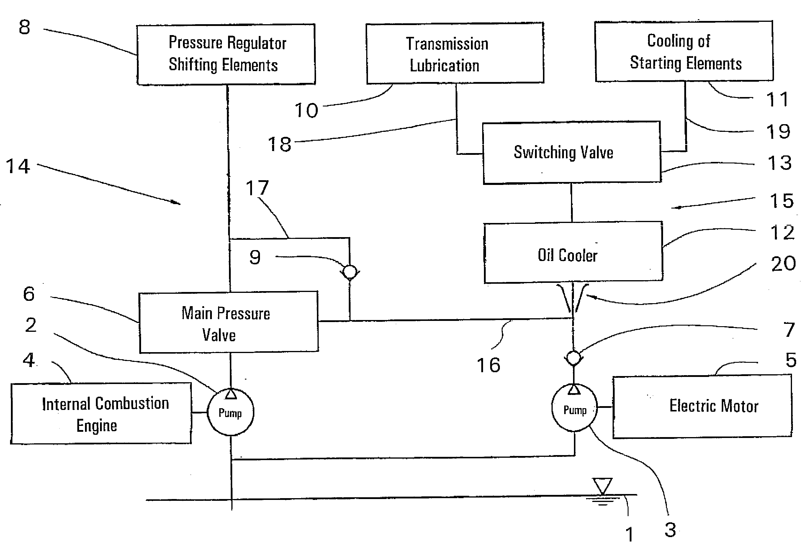
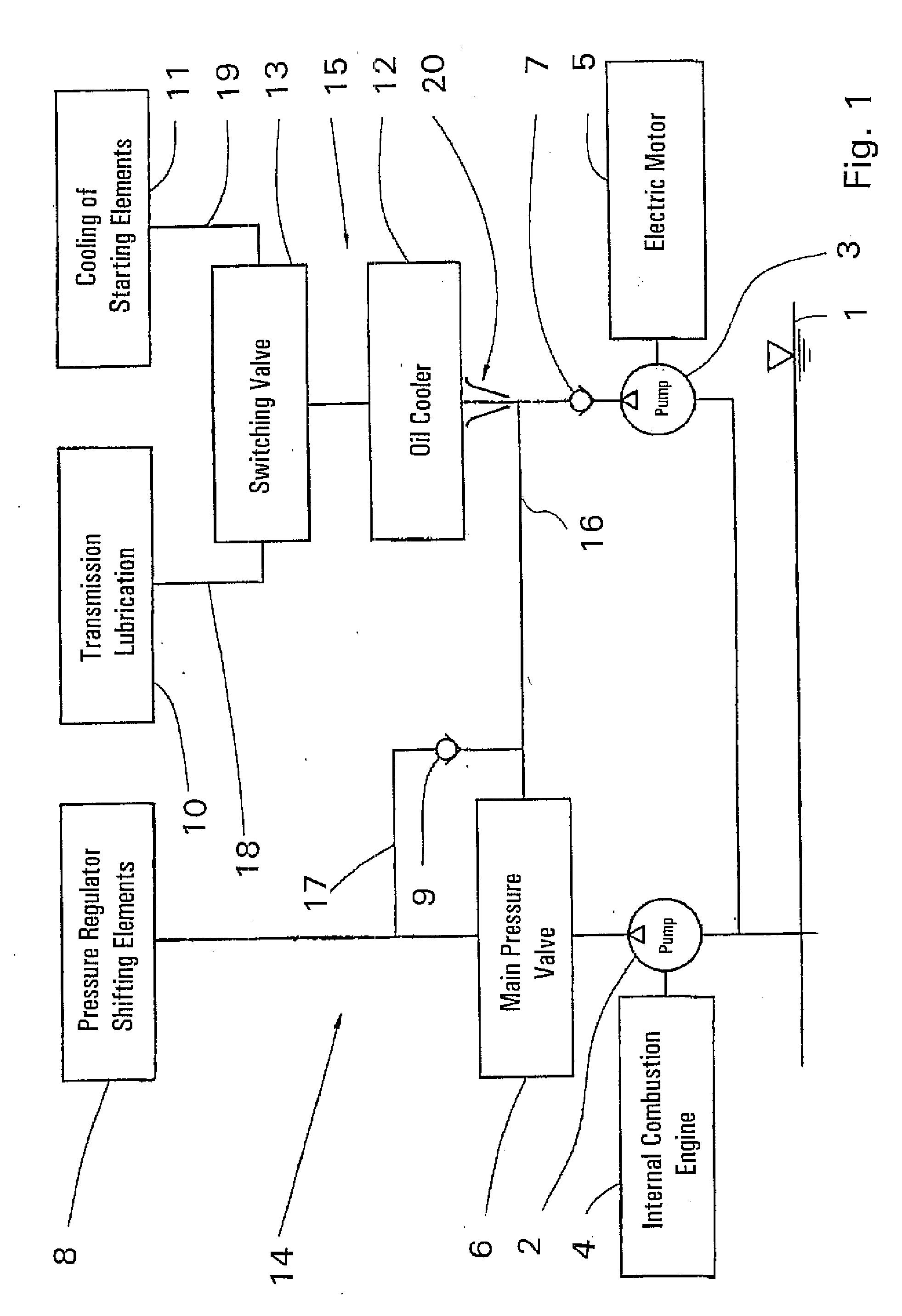
[0081]The oil supply system is comprised of a main pressure branch 14 on the left and a low pressure branch 14 on the right. From a common oil reservoir 1, which can be, for instance, the oil sump for a transmission and / or an oil-cooled friction clutch, a branched oil line leads to the intake of two oil pumps, where the first oil pump 2 is mechanically driven by an internal combustion engine 4, and the second oil pump 3 is electrically driven by an electric motor 5. The discharge or pressure branches of the pumps 2 and 3 can be connected to each other through a main pressure valve 6, whereas a first check valve 7, which is installed downstream of the electrically driven oil pump 3, prevents the backflow of oil through the oil pump 3 into the reservoir1, even when the electric motor 5 is switched off.

[0082]Oil pumps 2, 3 are both connected to the main pressure valve 6 and shifting elements 8 or other hydraulic control devices, which are connected, for instance, to hydraulic actuators...


PUM


Abstract

A method and a device for controlling the oil supply of an automatic transmission (gearbox) and to a starting element. The method can guarantee a sufficient supply of oil to a hydraulic control unit of the automatic transmission and / or the starting element, in particular an oil-cooled friction clutch, both during the operation of the internal combustion engine (4) and when the latter is at a standstill with the aid of an oil pump (2) that can be mechanically driven by the internal combustion engine (4) and a second oil pump (3) that can be electrically driven. In addition, the cooling oil supply of the starting element is guaranteed by the provision of a low-pressure oil by way of the electrically driven oil pump (3), at least during the starting operation, the stream cooling the starting element (11).

Description

[0001]This application is a national stage completion of PCT / EP2006 / 002106 filed Mar. 8, 2006, which claims priority from German Application Serial No. 10 2005 013 137.9 filed Mar. 22, 2005.FIELD OF THE INVENTION[0002]The invention concerns a method and arrangement for controlling the oil supply of an automatic transmission and a starting element.BACKGROUND OF THE INVENTION[0003]Automatic transmissions have been in use for some time, in particular in motor vehicles, to convert an input speed supplied by a vehicle's prime mover and / or an internal combustion engine into an output speed used for driving the wheels, where the driver is relieved, at least for the most part, from selecting the appropriate gear ratio.[0004]The gear ratios of these automatic transmissions can be infinitely variable or can have individual transmission ratios with predetermined gear ratios. For the most part, they are shifted by way of hydraulic shifting elements, which require an oil supply that has a suffic...

Claims


Application Information

Patent Timeline
Patent Type & Authority Applications(United States)
IPC IPC(8): F04B35/01F04B35/04F01P3/00F16H57/04
CPCF16H57/0434F16H61/0031Y10T477/6939F16H2312/14F16H2061/0037
Inventor REISCH, MATTHIASDREIBHOLZ, RALFGUMPOLTSBERGER, GERHARD
Owner ZF FRIEDRICHSHAFEN AG
Why Eureka
Try Eureka