Electronic device and on-vehicle module

a technology of electronic devices and on-board modules, applied in the direction of coupling device connections, printed element electric connection formation, securing/insulating coupling contact members, etc., can solve the problems of reduced connection reliability, increased value, and insufficient study of connection reliability, and achieve the effect of reducing the reliability of the board and high reliability of the press-fit connection

Inactive Publication Date: 2009-09-17
HITACHI LTD
View PDF11 Cites 7 Cited by
  • Summary
  • Abstract
  • Description
  • Claims
  • Application Information

AI Technical Summary

Benefits of technology

[0004]However, in the above-mentioned prior art, attention is paid to the problems occurring upon the press-fit connection but the connection reliability thereof is not sufficiently studied. The inventors pay attention to the high reliability of the press-fit connection and have performed various studies. FIG. 2(a) shows a sectional SEM (Scanning Electron Microscope) photograph of the connection part after the pin terminal 1 is press-fit into the through-hole and FIG. 2(b) shows the vicinity of the through-hole of the board on an enlarged scale. As shown in FIG. 2(b), delamination in i

Problems solved by technology

However, in the above-mentioned prior art, attention is paid to the problems occurring upon the press-fit connection but the connection reliability thereof is not sufficiently studied.
However, formation of the compound is advanced after the heat cycle test and delamination is formed at the interface as shown in FIG. 2(d), so that it is apprehended that resistanc

Method used


Image

  • Electronic device and on-vehicle module
  • Electronic device and on-vehicle module
  • Electronic device and on-vehicle module

Examples


experimental example 1

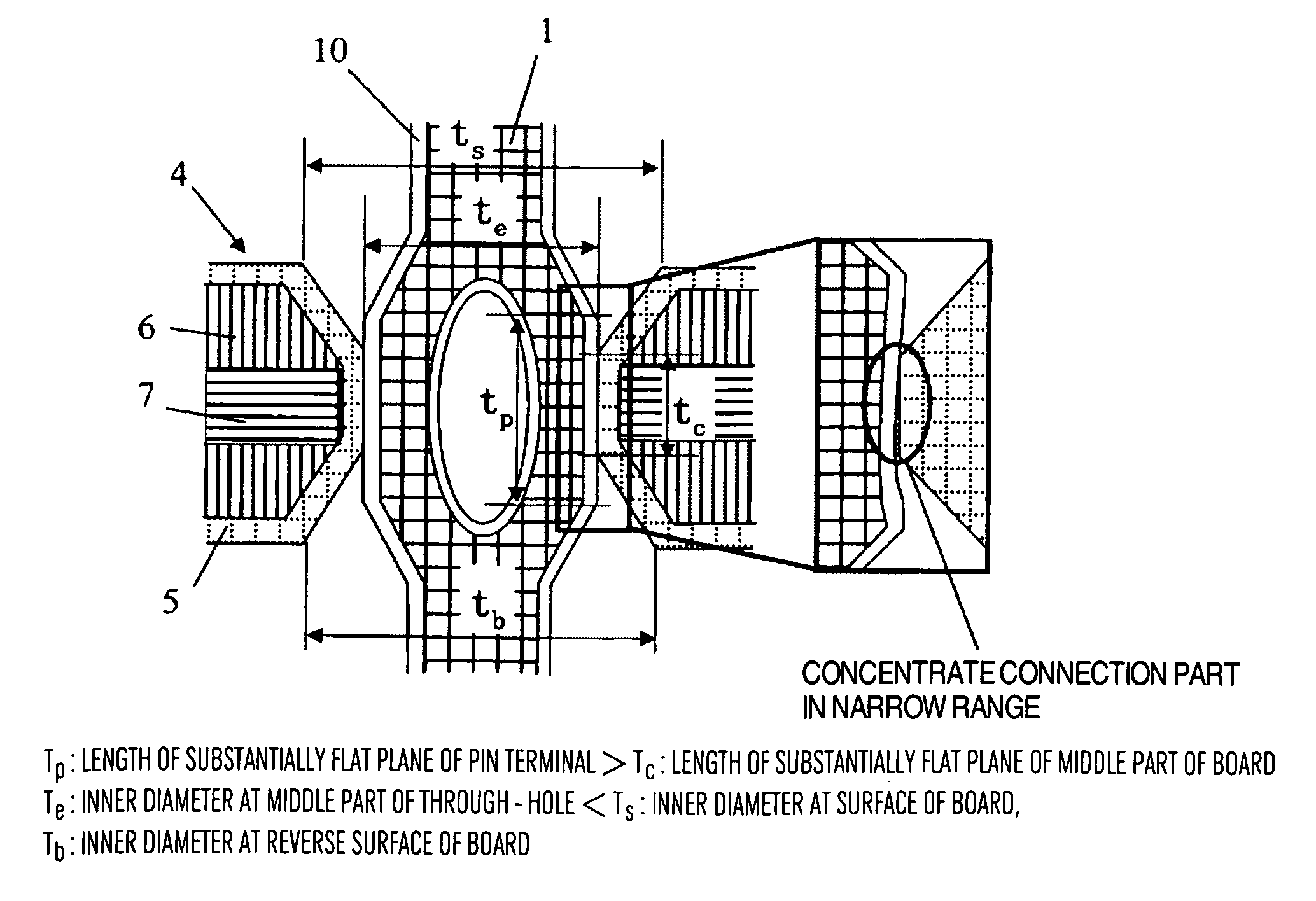
[0041]The pin terminal was made of P bronze and had the external shape of 1.2 mm (in the separation direction)×0.65 mm (in the thickness direction) and the length of the flat plane of 0.75 mm. The surface of the pin terminal was plated with Sn. The board had the thickness of 1.6 mm and the thickness of the portion connected to the pin terminal, of the core material of the through-hole, was equal to about 0.5 mm. The inner diameter of the through-hole was gradually increased from the core material toward the obverse and reverse surfaces of the board in a tapered manner.

[0042]As a result of observation of the external appearance for a test piece after the pin terminal was press-fit, the flat plane of the pin terminal was deformed to be bent convexly toward the inside of the pin terminal. As a result of observation of the section of the through-hole, delamination and whitening phenomenon were not found in the insulating resin near the through-hole. Furthermore, Sn of plating and Cu of ...

experimental example 2

[0044]The pin terminal had the same structure as described in the experimental example 1. The pin terminal was made of P bronze and had the external shape of 1.2 mm (in the separation direction)×0.65 mm (in the thickness direction) and the length of the flat plane of 0.75 mm. The surface of the pin terminal was plated with Sn. The board had the thickness of 1.6 mm and the thickness of the portion connected to the pin terminal of the core material of the through-hole was equal to about 0.5 mm. The inner diameter of the through-hole was gradually increased from the core material toward the obverse and reverse surfaces of the board in a tapered manner.

[0045]As a result of observation of the external appearance for a test piece after the pin terminal was press-fit into the through-hole, the flat plane of the pin terminal was deformed to be bent convexly toward the inside of the pin terminal. As a result of observation of the section of the through-hole, delamination and whitening phenom...


PUM

PropertyMeasurementUnit
Fractionaaaaaaaaaa
Lengthaaaaaaaaaa
Thicknessaaaaaaaaaa

Abstract

In a module, press-fit connection using a pin terminal including a connection part separated into two parts and a flat plane parallel to the lengthwise direction in the separation part and perpendicular to the separation direction of the pin terminal is performed. A through-hole of a board is structured so that an inner diameter of the through-hole at a middle part in the thickness direction of the board is smaller than that at obverse and reverse surfaces of the board and the length of the middle part of the through-hole connected to the pin terminal is shorter than the length of the flat plane of the pin terminal.

Description

BACKGROUND OF THE INVENTION[0001]The present invention relates to an electronic device and particularly an on-vehicle module provided with a board having through-holes to which pin terminals (wiring pins and connector pins) of another substrate or module are connected in a press-fit manner.[0002]Recently, as a connection form in case where components are mounted on a board in which electrical wiring is formed, the press-fit connection is increasingly being adopted in which as shown in FIG. 1A a plurality of pin terminals 1 mounted in a press-fit connector 3 of a component are press-fit into a plurality of through-holes 8 formed in a board 4 so that the pin terminals 1 are mechanically connected to wiring in the through-holes 8 to thereby make electrical connection therebetween. Since an outer diameter of a connection part 2 of each pin terminal 1 is larger than an inner diameter of each through-hole and the connection part is resiliently deformed by external force, the outer diamete...

Claims


Application Information

Patent Timeline
IPC IPC(8): H01R12/00
CPCH05K1/0366H05K1/056H05K1/119H05K1/141H05K3/308H05K3/42Y10S439/941H05K2201/09854H05K2201/10189H05K2201/10446H05K2201/1059H05K2201/10803H05K2201/09827
Inventor YAMASHITA, SHIROYOSHINARI, HIDETO
Owner HITACHI LTD
Why Eureka
Try Eureka