Hollow speed reducer

a technology of speed reducer and speed reduction plate, which is applied in the direction of gearing, oblique crank gearing, wobble plate gearing, etc., can solve the problem that the turning structure cannot be downsized, and achieve the effect of reducing the length in the axial direction of the turning structure, facilitating manufacturing thereof, and not significantly changing the structure per s

Active Publication Date: 2009-09-17
NABLESCO CORP
View PDF8 Cites 13 Cited by
  • Summary
  • Abstract
  • Description
  • Claims
  • Application Information

AI Technical Summary

Benefits of technology

[0010]According to the invention, a plurality of drive motors can be constituted, an individual drive motor can be downsized, whereby a length in an axial direction of a turning structure can be shortened.
[0011]Further, according to the invention, a speed reducer used in a background art can be used as it is, the structure per se is not considerably changed and manufacturing thereof is facilitated.
[0012]Further, according to the invention, a plurality of motors are used, and therefore, even when one of the plurality of motors is failed, the machine can continuously be driven by a remaining motor. Thereby, even when a robot is failed, a time period of stopping a manufacturing line can be reduced more than that of the background apparatus.
[0013]Further, in an operation of interchanging a portion of motors by a failure or the like, currently, a mechanical lock is separately prepared between a pivoting portion and a fixed portion in the motor interchanging operation. In contrast thereto, according to the invention, a motor which is not interchanged can be utilized as an attitude maintaining brake, and by utilizing the motor which is not interchanged as the attitude maintaining brake in this way, the interchanging operation can be carried out without preparing the mechanical lock as described above, and the operation is extremely facilitated. Further, at this occasion, all of the motors are not completely detached, and therefore, according to the speed reducer of the invention, an original point returning operation of the robot can extremely easily be carried out.

Problems solved by technology

According to the speed reducer disclosed in Patent Reference 1, there is a problem that the motor is large-sized, and therefore, a turning structure is large-sized, particularly, a length in an axial direction is large.
Therefore, there is still other problem that the turning structure cannot be downsized.

Method used


Image

  • Hollow speed reducer
  • Hollow speed reducer
  • Hollow speed reducer

Examples


Embodiment Construction

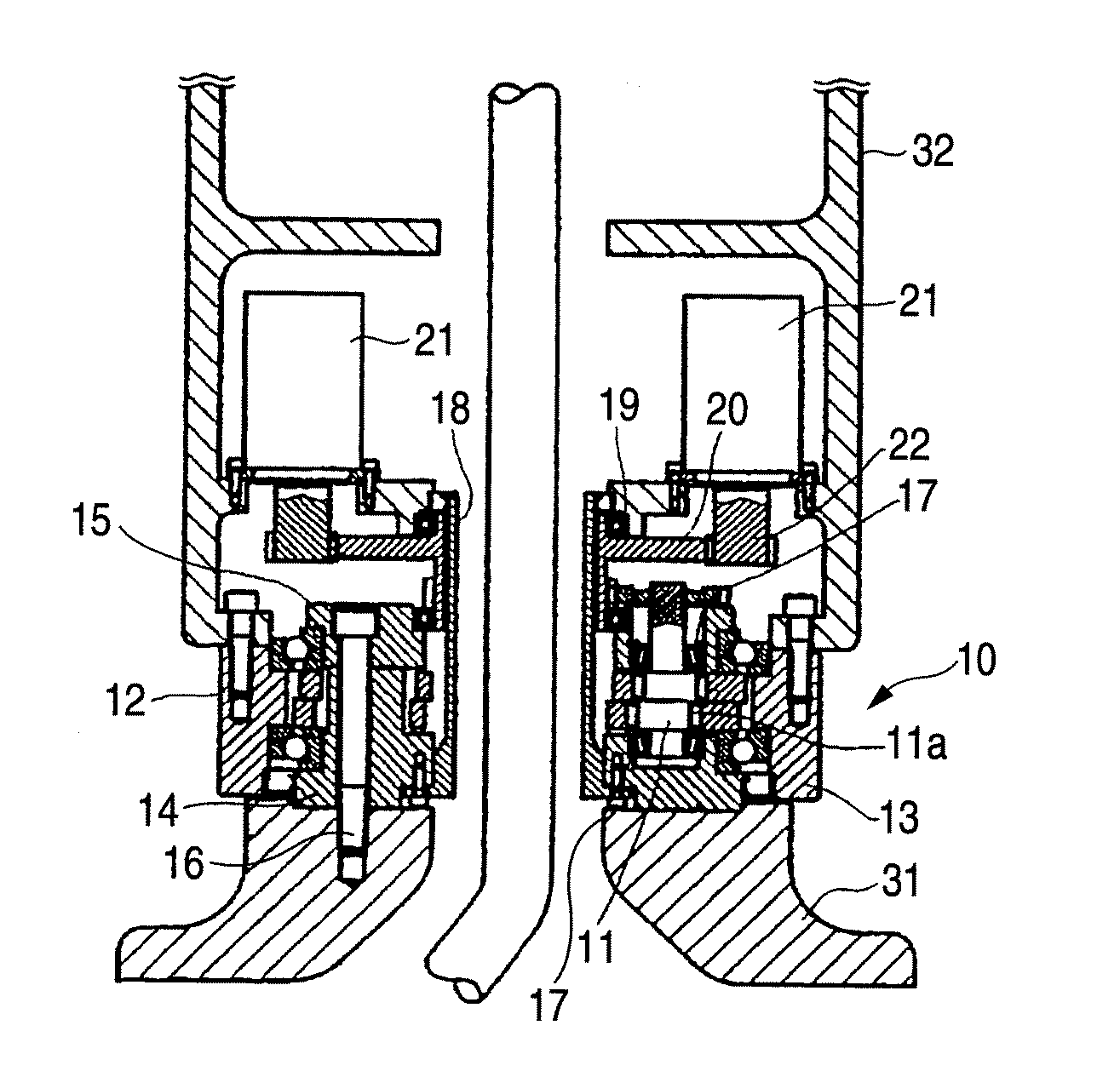
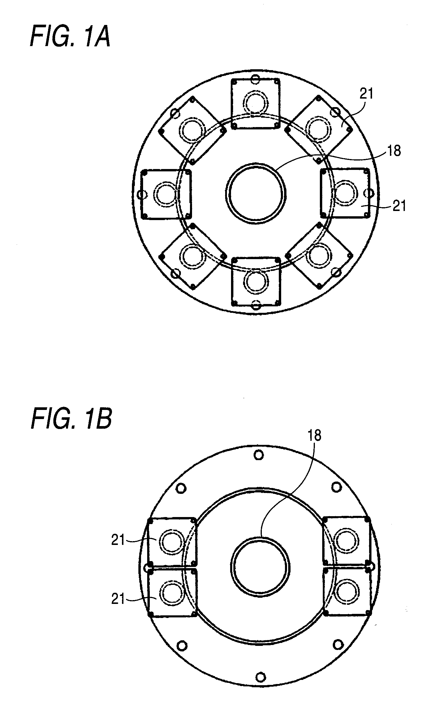
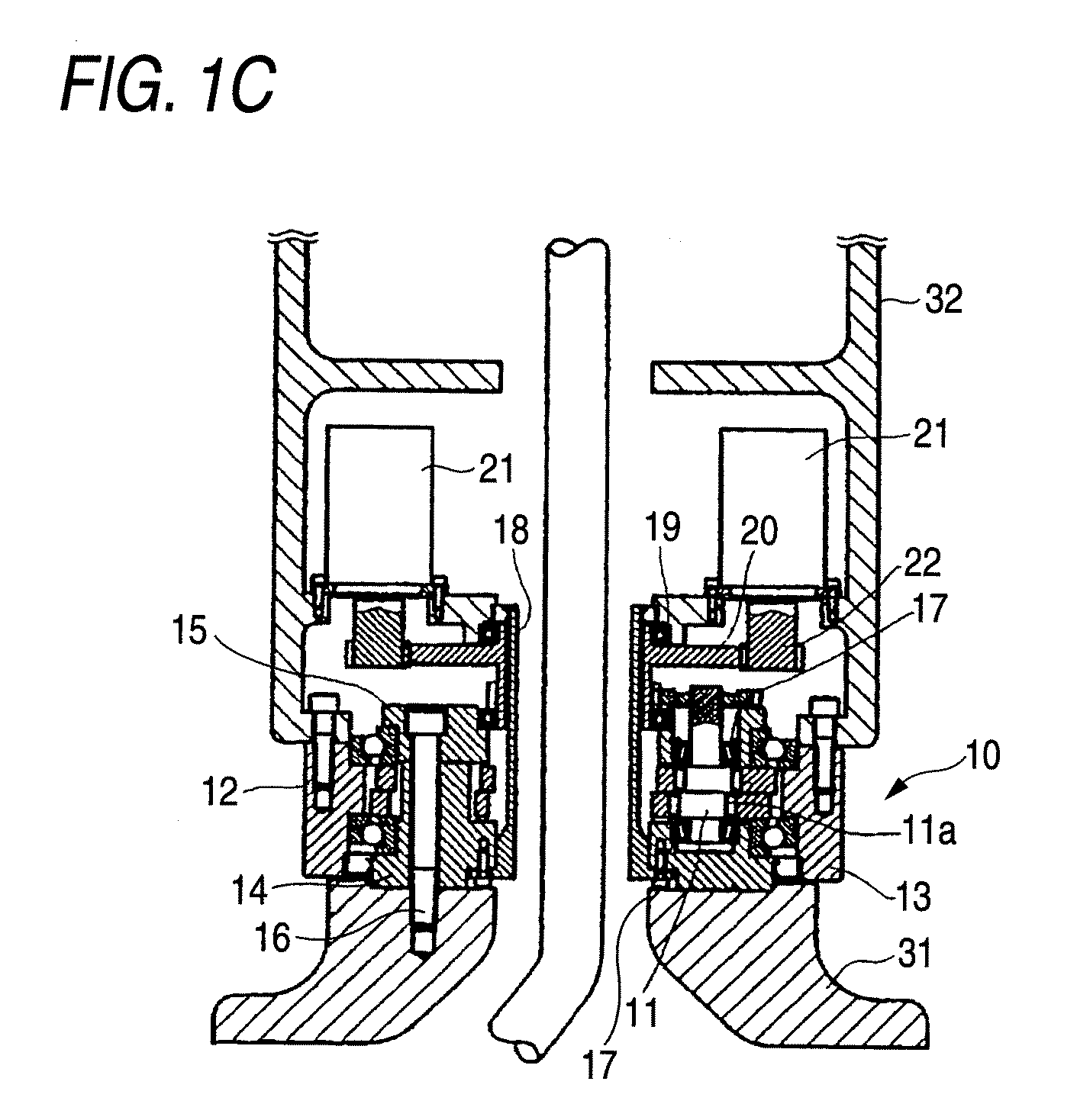
[0020]A number of embodiments of the invention will be explained in reference to the attached drawings as follows. FIGS. 1A through C show an embodiment of constituting a turning mechanism of a robot arm by using a planetary gear apparatus as a hollow speed reducer according to the invention, FIG. 1A is a plan view of a first embodiment, FIG. 1B is a plan view of a second embodiment, and FIG. 1C is a vertical sectional view of the first or the second embodiment.

[0021]In FIG. 1C, a hollow speed reducer 10 of the embodiment is a planetary gear apparatus comprising a crankshaft 11, a pinion 12 formed with outer teeth at an outer periphery thereof, fitted to a crank portion 11a of the crankshaft and eccentrically moved, and a case 13 an inner peripheral face of which is formed with inner teeth brought in mesh with the outer teeth of the pinion 12. The pinion 12 includes the outer teeth of a tooth shape comprising an equal distance curve to a pericycloidal curve at an outer peripheral fa...


PUM


Abstract

There is provided a speed reducer capable of shortening a length in an axial direction of a turning structure by arranging a plurality of small-sized motors.
A hollow speed reducer 10 is a planetary gear apparatus comprising a crankshaft 11, a pinion 12 formed with outer teeth at an outer periphery thereof, fitted to a crank portion of the crank shaft 11 and eccentrically moved, and a case 13 an inner peripheral face of which is formed with inner teeth brought in mesh with the outer teeth of the pinion 12, in which an inner portion of the hollow speed reducer 10 is formed with a hollow hole, a center gear for an input of the hollow speed reducer 10 is provided at a position of the hollow hole, and small gears provided at output shafts of a plurality of motors are simultaneously brought in mesh with the center gear.

Description

TECHNICAL FIELD[0001]The present invention relates to a speed reducer used for a turning structure of a robot or reducing a speed of a motor output, further in details, relates to a hollow speed reducer including a hollow hole at a center portion of the speed reducer.BACKGROUND ART[0002]There is such a hollow speed reducer disclosed in, for example, Patent Reference 1 (JP-A-7-108485). According to Patent Reference 1, there is disclosed a rotation joint of a robot or the like characterized in a rotation joint of a robot or the like for decelerating a rotation output of a drive motor and rotating a rotation portion around a rotation axis center relative to a fixed portion, constituted by an outer bearing apparatus including a hollow speed reducer having an output portion for decelerating a rotation drive force of the drive motor to a rotation output around a predetermined axis center to transmit to the rotation portion and including a hollow cylindrical hole at a center portion, an ou...

Claims


Application Information

Patent Timeline
Patent Type & Authority Applications(United States)
IPC IPC(8): F16H1/32F16H57/021
CPCF16H1/32F16H37/065Y10T74/19H02K7/116H02K16/00F16H49/001
Inventor NAKAMURA, KOJI
Owner NABLESCO CORP
Why Eureka
Try Eureka