Mechanism for Osteosynthesis

Inactive Publication Date: 2009-09-17
HIDETOSHI ONOUE +1
View PDF14 Cites 72 Cited by
  • Summary
  • Abstract
  • Description
  • Claims
  • Application Information

AI Technical Summary

Benefits of technology

[0016]The mechanism for osteosynthesis makes it possible to easily pull bone fragments apart from each other and nearer toward each other by utilizing a cam mechanism. The bone plate enables it to use the cam mechanism of a relatively simple structure, and therefore helps reduce the manufacturing cost of the mechanism for osteosynthesis.
[0017]According to the first and second mechanism for osteosynthesis of present invention, it is made possible to finely adjust the amount of movement of the bone fragment by the amount of rotating the pin, and to easily quantify the amount of movement of the fractured bone in terms of the change in the position of the pin or the amount of ro

Problems solved by technology

However, fractured bones are often in a state different from that before fracture.
For example, a tendon attached to the bone may pull a part of the fractured bone to cause it to overlap with the other part of the bone resulting in shortening dislocation, or the fractured parts of the bone may be pulled apart from each other resulting in a gap (separating dislocation).
However, the bone coaptation surgery based on this technique is not capable of reliably rectifying the dislocation in the fractured bone by means of fingers or making fine adjustment during

Method used


Image

  • Mechanism for Osteosynthesis
  • Mechanism for Osteosynthesis
  • Mechanism for Osteosynthesis

Examples


first embodiment

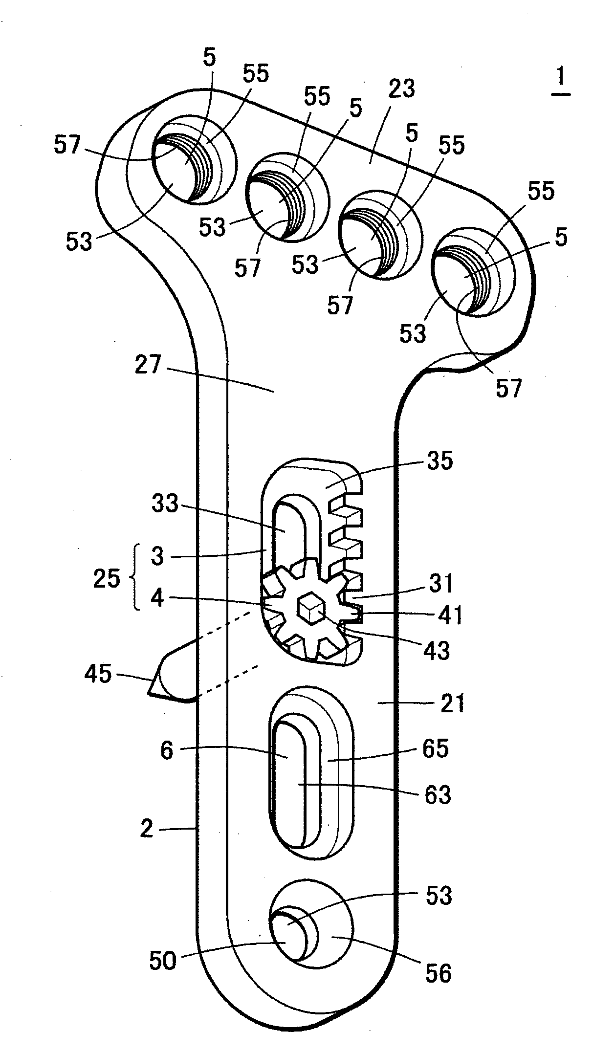
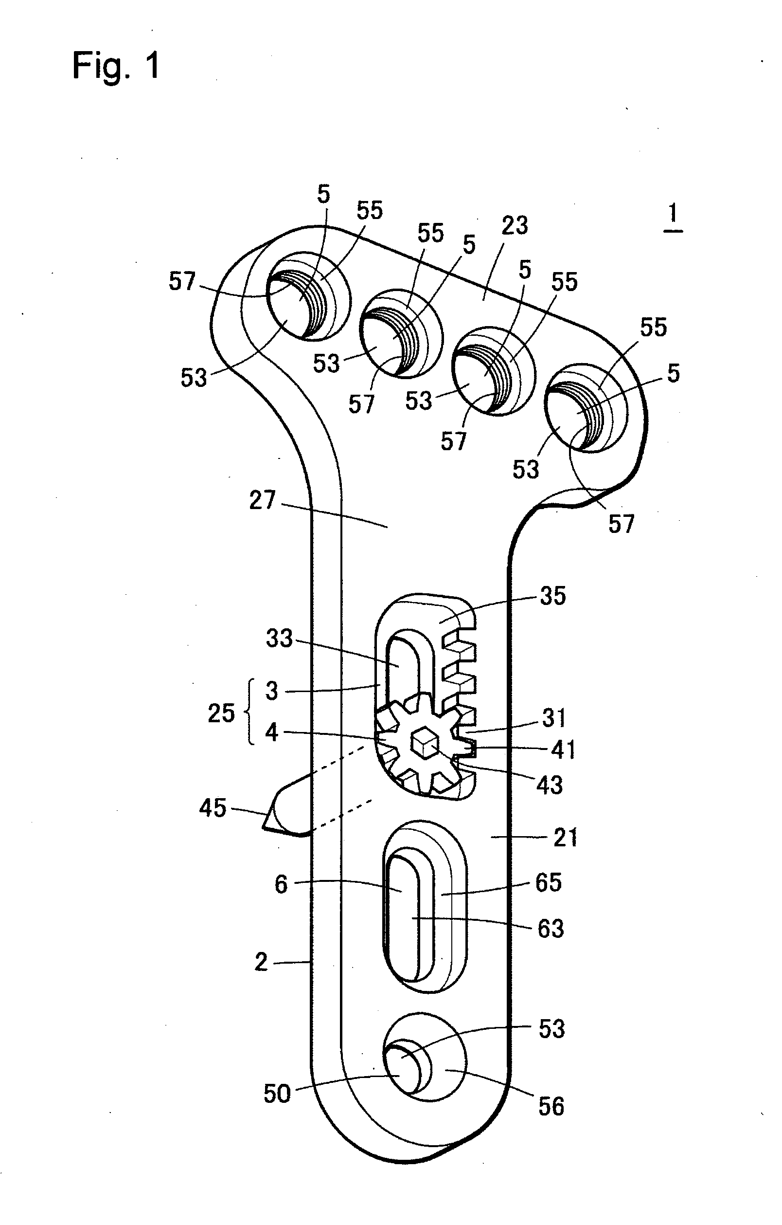
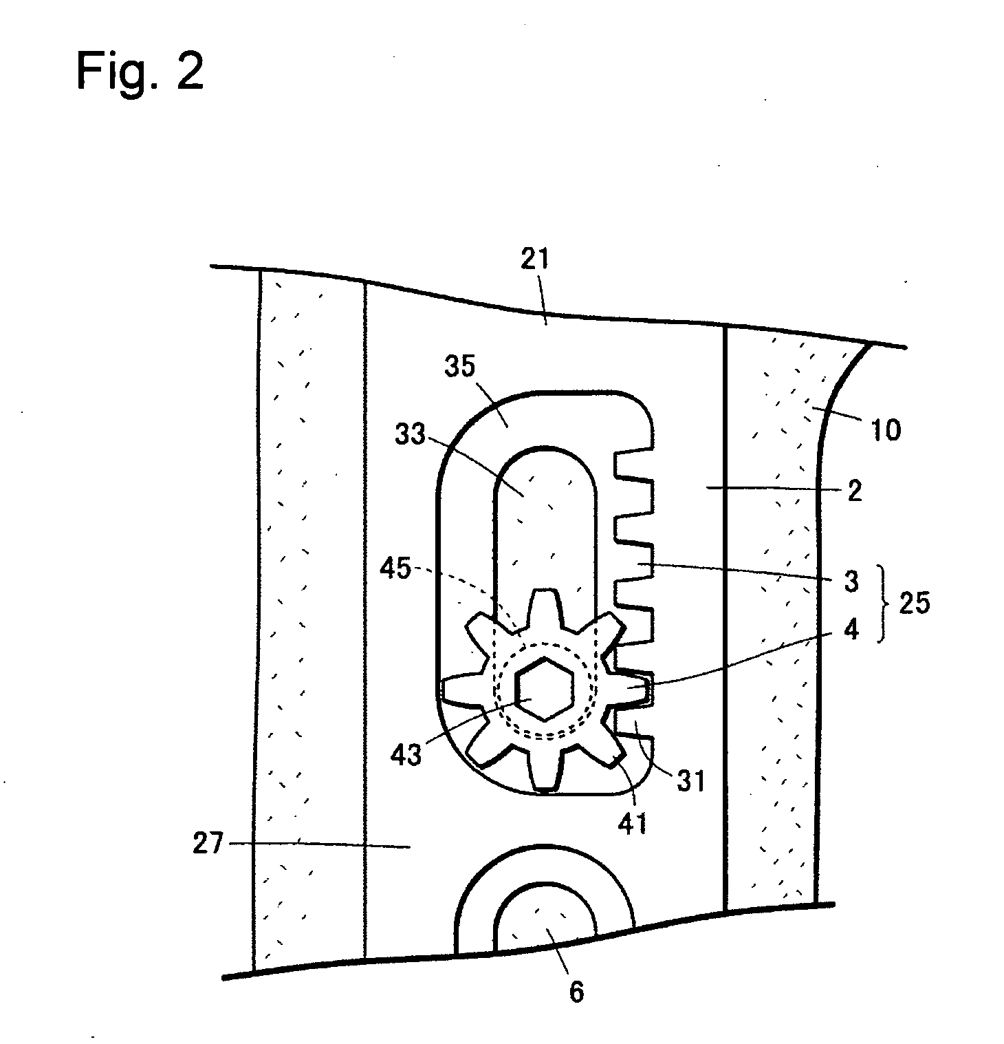
[0067]FIG. 1 and FIG. 2 show a mechanism for osteosynthesis (bone fixture) 1 used in fixation of a distal end of radius, among the mechanism for osteosynthesis provided with a gear mechanism according to the present invention. A plate part (a bone plate) 2 of the mechanism for osteosynthesis 1 of this embodiment is a substantially T-shaped plate extending longer in one direction, constituted from a slender diaphyseal fixing portion 21 and an epiphysial fixing portion 23 that is fixed on the top end of the diaphyseal fixing portion 21 in lateral direction.

[0068]The diaphyseal fixing portion 21 has a sliding elongate hole 3, an auxiliary sliding elongate hole 6 and a through hole 50 with a spherical bearing surface.

[0069]The sliding elongate hole 3 extends along the longitudinal direction of the bone plate 2 of the mechanism for osteosynthesis 1, and consists of a countersunk portion 35 of rectangular shape having four rounded corners formed on a surface 27 of the mechanism for osteos...

second embodiment

[0105]The mechanism for osteosynthesis of the present invention can be made in such a form that can be applied to the fracture of various bones such as humerus, forearm (including radius and ulna), vertebra, femur, crus (including tibia and fibula), phalanges of hand and phalanges of foot, in addition to radius as in the first embodiment. One form of the mechanism for osteosynthesis of the present invention will be described below.

[0106]FIG. 6A shows a mechanism for osteosynthesis 100A to be used in proximal side of forearm bone where the epiphysial fixing portion 23 of the bone plate 2 is fixed onto the epipysis of the humerus and the diaphyseal fixing portion 21 of the bone plate 2 is fixed onto the diaphysis of the humerus. The mechanism for osteosynthesis 100A comprises the bone plate 2, the sliding elongate hole 3 formed in the bone plate 2, a plurality of female-threaded holes 5 (arranged in 2 rows and 3 columns in rectangular configuration in this example), a plurality of aux...

third embodiment

[0109]FIG. 6B shows a mechanism for osteosynthesis 100B to be used in distal side of femur, where the epiphysial fixing portion 23 of the bone plate 2 is fixed onto the epiphysial part of the femur and the diaphyseal fixing portion 21 of the bone plate 2 is fixed onto the diaphysis of the femur. The mechanism for osteosynthesis 100B comprises the bone plate 2, the sliding elongate hole 3 formed in the bone plate 2, a plurality of female-threaded holes 5 (6 holes are arranged in triangular configuration in this example), a plurality of auxiliary sliding elongate holes 6 (two in this example), the hole 50 with the spherical bearing surface and the pinion pin 4 to be fitted in the sliding elongate hole 3.

[0110]Method of using the mechanism for osteosynthesis 100B shown in FIG. 6B is similar to that of the first and second embodiments. The method comprises (1) fixing the epiphysial fixing portion 23 on the epiphysial part of the fractured bone; (2) fixing the auxiliary sliding elongate ...


PUM


Abstract

A mechanism for osteosynthesis 1 is provided that is capable of finely adjusting the amount of movement of a fractured bone, quantifying the amount of the movement and can be used both in pulling the fractured bones apart from each other and pulling the fractured bones nearer toward each other. A first mechanism for osteosynthesis 1 of the present invention comprises a plate part 2 for reducing two or more fractured bones monolithically by fixing at least both ends of the plate part 2 on the fractured bones and a sliding part 25 for moving one fractured bone along a sliding elongate hole 3 formed in the plate part 2 so as to elongate from the one fractured bone toward another fractured bone, the sliding part 25 comprising a rack 31 formed on an inner surface of the sliding elongate hole so as to extend along a sliding direction and a pin inserted in the sliding elongate hole 3, the pin 4 having a head portion 41 having a pinion for engaging with the rack 31 and a base portion 45 to be inserted into the one fractured bone, wherein the sliding part 25 moves the one fractured bone slidably along the sliding elongate hole 3 by rotating the pin 4.

Description

BACKGROUND OF THE INVENTION[0001]1. Field of the Invention[0002]The present invention relates to a mechanism for osteosynthesis used for reducing and fixing fractured bones monolithically and promoting coaptation of the bone, in the event of fracture or osteotomy in diaphysis and epipysis.[0003]2. Description of the Related Art[0004]In case a part of a fractured bone is separated from the rest of the fractured bone, such an operation is performed as the separated part of the bone is replaced at the original position so as to promote coaptation of the fractured bones. One method of holding the separated part of a fractured bone at the original position for reduction is to keep the fractured bones together by means of a mechanism for osteosynthesis that employs such a member as bone plate that extends from the separated part of the fractured bone over the rest of the fractured bone. The separated part of the fractured bone, as it is kept together with the rest of the fractured bone mo...

Claims


Application Information

Patent Timeline
IPC IPC(8): A61B17/58A61B17/80
CPCA61B17/8004A61B17/8605A61B17/8014A61B17/8009
Inventor ONOUE, HIDETOSHIITO, JUNJIIKEDA, TORU
Owner HIDETOSHI ONOUE
Why Eureka
Try Eureka