Demand control device

a demand control and control device technology, applied in the direction of load forecast in ac network, process and machine control, instruments, etc., can solve the problems of inability to predict the demand control issue time and the demand control duration, and inability to reduce the power consumption integrated value within the demand time interval

Inactive Publication Date: 2009-09-17
SANYO ELECTRIC CO LTD
View PDF8 Cites 84 Cited by
  • Summary
  • Abstract
  • Description
  • Claims
  • Application Information

AI Technical Summary

Benefits of technology

[0011]A demand control device according to a second aspect of the present invention is a demand control device applied in a facility provided with a plurality of power-consuming appliances, the demand control device including a unit arranged to store performance data of a power consumption integrated value for each individual environmental condition in a power database, a predicted value calculating unit arranged to calculate a predicted value of the power consumption integrated value for each one of a current demand time interval and a demand time interval subsequent to the current demand time interval based on the performance data stored in the power database at a start of the demand time interval, and a control unit arranged to control the appliances based on the predicted value calculated by the predicted value calculating unit for each one of the plurality of demand time intervals and on a pre-set target value, wherein the control unit includes a unit arranged to control, when the predicted value for the current demand time interval does not exceed the target value, and the predicted value for the subsequent demand time interval exceeds the target value, an operation of at least one of the appliances which are continuously operated over the both demand time intervals such that an effect of operating the appliance is higher in the current demand time interval than during a normal operation.
[0012]In the demand control device according to the second inventive aspect, the appliance which is continuously operated over the both demand time intervals is, e.g., a temperature adjusting appliance. In this case, when the predicted value for the current demand time interval does not exceed the target value, and the predicted value for the subsequent demand time interval exceeds the target value, the control unit changes a set temperature of the temperature adjusting appliance such that an effect of operating the appliance is higher in the current demand time interval than during a normal operation.

Problems solved by technology

In some cases, it is impossible to reduce the power consumption integrated value within the demand time interval to a value not more than the target value.
However, it is unknown how to predict the demand control issue time and the demand control duration based on the demand value, the outside air temperature data, and the humidity data obtained at the air-cooled place.
It is also unknown how to calculate the excessive cooling set temperature, the excessive cooling required period, and the excessive cooling start time.

Method used


Image

  • Demand control device
  • Demand control device
  • Demand control device

Examples


Embodiment Construction

[0031]Referring now to the drawings, an embodiment of the present invention will be described hereinbelow.

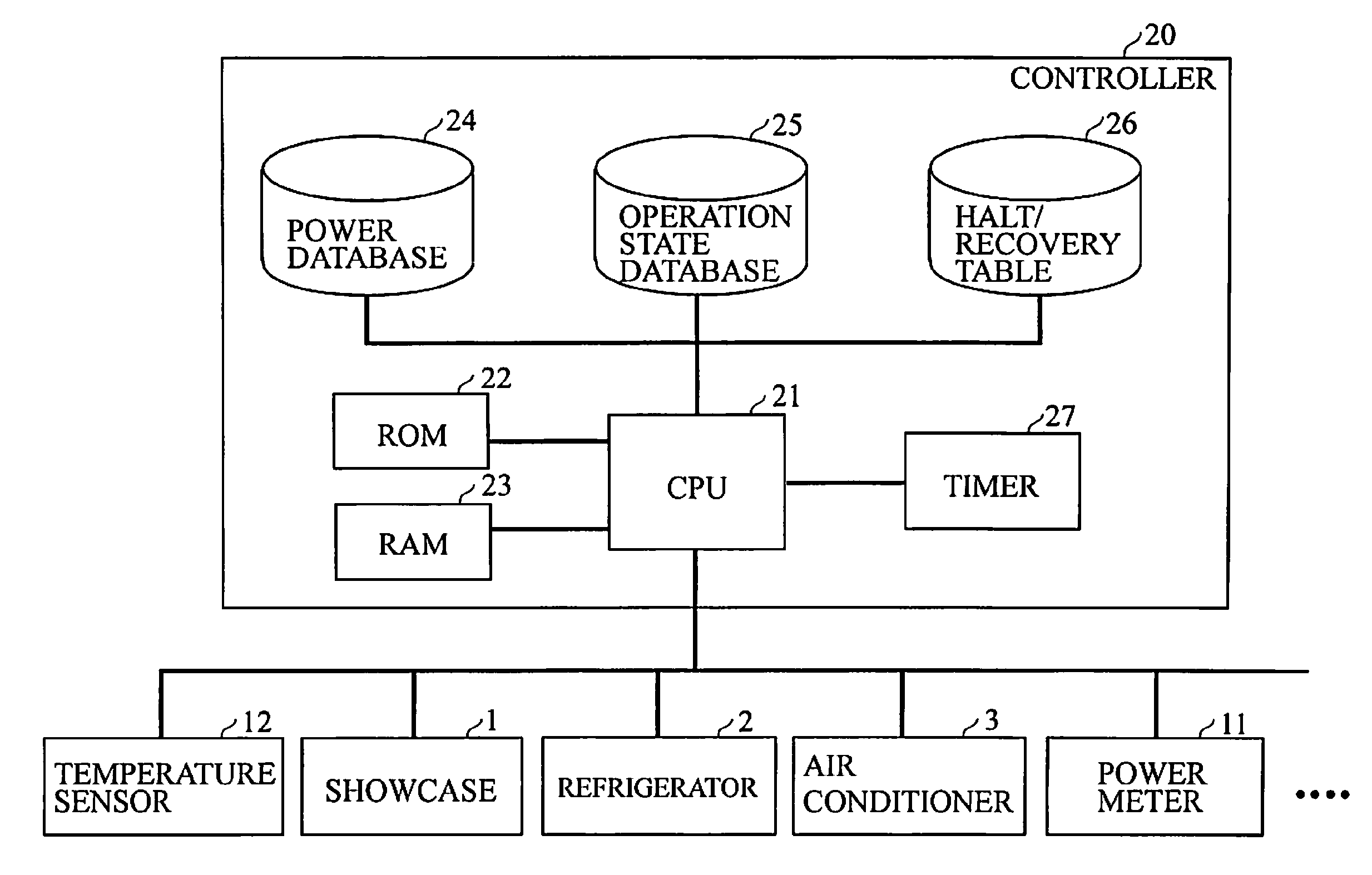
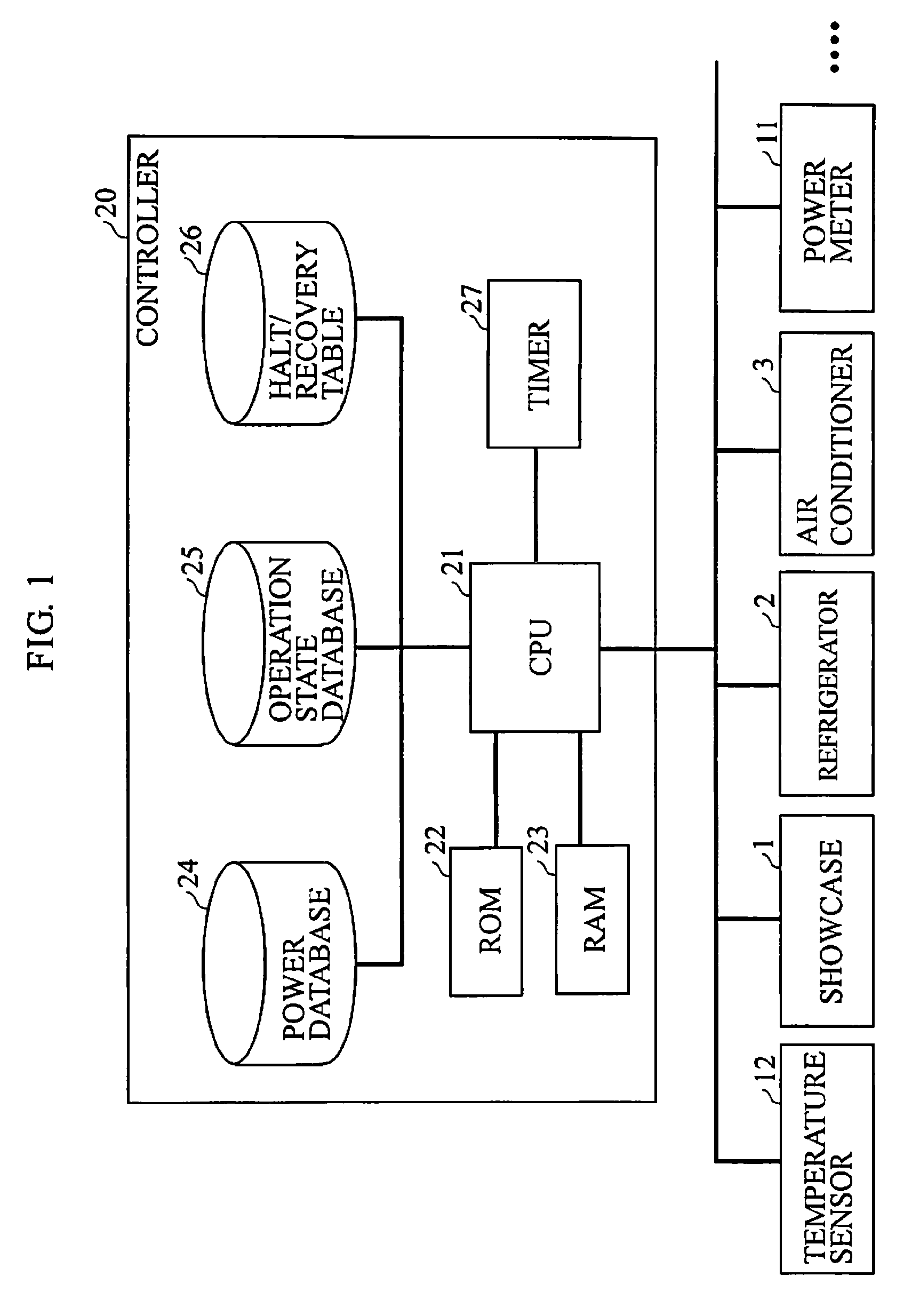
[0032]FIG. 1 shows power-consuming appliances provided in a store such as a supermarket, and a controller for centralized control of those appliances.

[0033]The controller 20 is connected to each of the power-consuming appliances arranged in the store, e.g., a showcase 1, a refrigerator 2, an air conditioner 3, and the like. The controller 20 is also connected to a power meter 11 which measures electronic power consumption. The controller 20 is further connected to a temperature sensor 12 for measuring an outside air temperature.

[0034]The controller 20 includes a CPU 21. The CPU 21 is connected to a ROM 22 which stores a program thereof or the like, a RAM 23 which stores necessary data, a power database 24, an operation state database 25, a halt / recovery table 26, a timer 27, and the like. The power database 24, the operation state database 25, and the halt / recovery table 26 are ...


PUM


Abstract

A demand control device includes a predicted value calculating unit (21) arranged to calculate a predicted value of a power consumption integrated value for each one of a plurality of demand time intervals including a current demand time interval and a predetermined number of demand time intervals subsequent to the current demand time interval based on performance data stored in a power database (24) at the start of the demand time interval, and a control unit (21) arranged to control appliances based on the predicted value calculated by the predicted value calculating unit (21) for each one of the plurality of demand time intervals and on a pre-set target value.

Description

TECHNICAL FIELD[0001]The present invention relates to a demand control device which predicts a power consumption integrated value in a demand time interval, and controls appliances based on a predicted value.BACKGROUND ART[0002]A demand-based contract system is available as a contract system for electricity rates, which is implemented between a store / facility owner and an electric power company. The demand-based contract system determines electricity rates based on the maximum integrated value of electric power consumed in demand time intervals in a year. In this system, a power consumption integrated value is calculated for each one of the predetermined demand time intervals, and the electricity rates are determined based on the maximum of the power consumption integrated values calculated for the respective demand time interval in a year. The demand time interval is a time period value such as 15 minutes or 30 minutes, or a time zone between 12:00 and 2:00 in which electric power ...

Claims


Application Information

Patent Timeline
Patent Type & Authority Applications(United States)
IPC IPC(8): G06F1/26
CPCH02J3/14H02J13/0017H02J2003/003Y04S40/12Y04S20/222Y02B90/2607Y02B70/3225H02J3/003H02J2310/12H02J13/00004H02J13/00006Y02B90/20Y02A30/60
Inventor OUCHI, ATSUSHINAKAJIMA, HIDEKI
Owner SANYO ELECTRIC CO LTD
Why Eureka
Try Eureka