
Fuel Injector Control Method

a fuel injector and control method technology, applied in the direction of electrical control, process and machine control, instruments, etc., can solve the problems of increasing smoke production, limiting the demand time, and large injection timing and other problems

Inactive Publication Date: 2009-09-17
DELPHI INT OPERATIONS LUXEMBOURG S A R L
View PDF6 Cites 5 Cited by
  • Summary
  • Abstract
  • Description
  • Claims
  • Application Information

AI Technical Summary

Benefits of technology

[0012]The present invention advantageously enables the ECM to operate with demand times between a...

Problems solved by technology

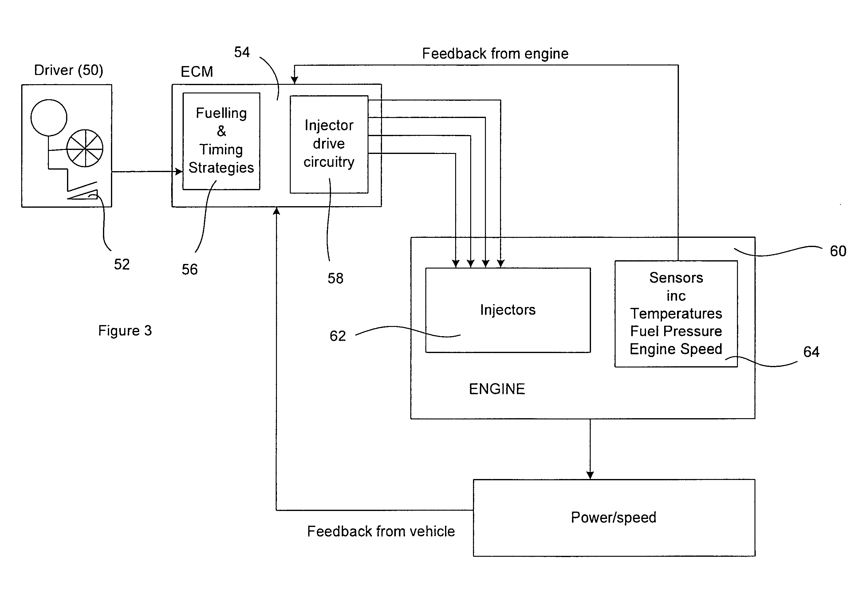
Such strategies determine the number, size and timings of the injections and tend to be large and complicated.
Although pilot injections are used in diesel engines to reduce combustion noise, they can lead to an increase in smoke production.
As a result, there is a limit to how short the demand time can be because it is governed by the time required to charge the stack fully, the time it takes to open the injector, and the time required for the switching means controlling the injection to switch on and off as appropriate.

Method used


Image

  • Fuel Injector Control Method
  • Fuel Injector Control Method
  • Fuel Injector Control Method

Examples


Embodiment Construction

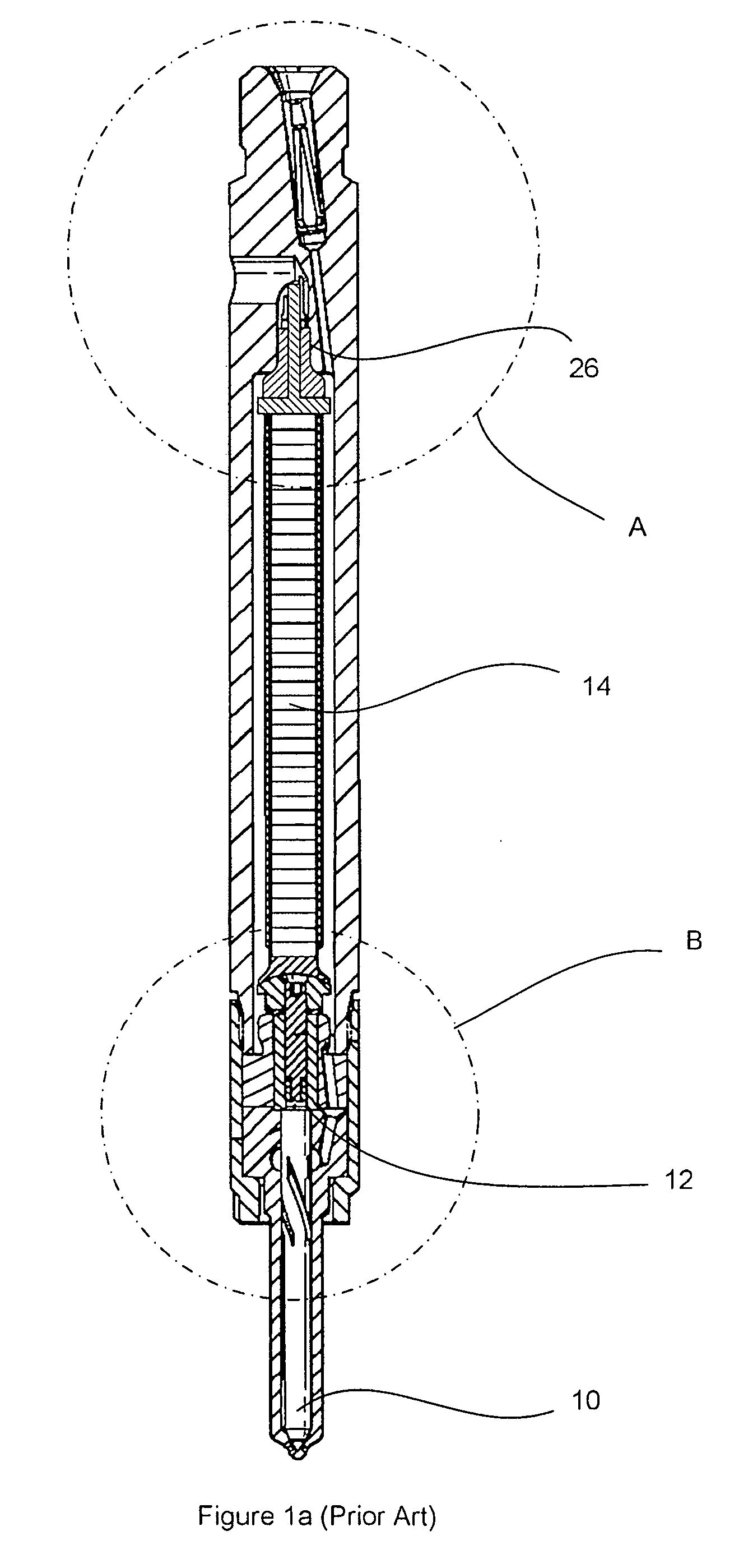
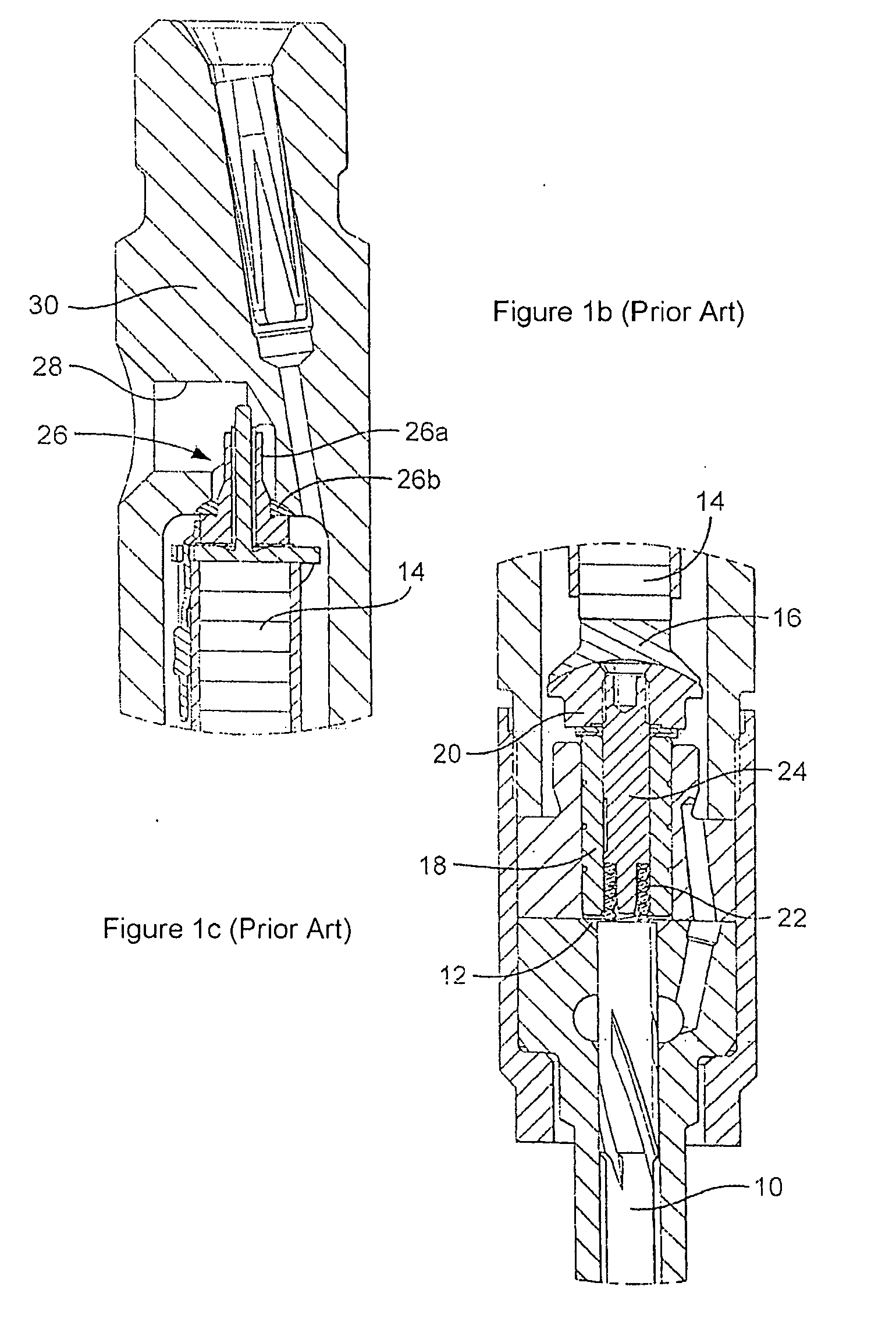
[0042]Referring to FIGS. 1a to 1c, a fuel injector of the piezoelectrically operable type typically includes a valve needle 10 that is engageable with a seating to control fuel delivery to an associated engine cylinder. A surface associated with the valve needle 10 is exposed to fuel pressure within a control chamber 12. The valve needle 10 is moveable between a first position, in which it is engaged with its seating, and a second position, in which the valve needle is lifted from its seating. When the valve needle 10 is in its first seated position fuel injection does not occur, and when it is moved away from its first position towards its second position injection is commenced. The injector receives fuel from a common rail source (not shown) of high-pressure fuel having a rail pressure, Rp, that is measured by a suitable sensor (not shown).

[0043]The injector includes a hydraulic amplifier arrangement including a control piston 18 that is operable to vary the volume of the control ...


PUM


Abstract

A fuel injector control method comprises determining a required separation time between a termination of an on signal associated with a first injection event and an initiation of an on signal associated with a second injection event. The method comprises calculating an overlap time between the separation time and the time to charge the piezoelectric stack to a first level; dividing the overlap time into first and second time periods as a function of the charge and discharge currents; applying the charge current to the piezoelectric stack for a charge time; and applying the discharge current to the piezoelectric stack for a discharge time so as to discharge the stack to a second level, wherein the discharge time is calculated on the basis of the second time period of the overlap time. Thus, first and second injection events are merged in a pulse mode of operation.

Description

FIELD OF THE INVENTION[0001]This invention relates to a control method for controlling operation of a fuel injector, specifically a piezoelectric fuel injector, for use in the delivery of fuel to a combustion space of an internal combustion engine. In particular, the invention relates to a method for controlling the time separation between a termination of one injection event and an initiation of a subsequent injection event.BACKGROUND OF THE INVENTION[0002]Piezoelectric fuel injectors are well-known for use in automotive engines and employ a piezoelectric actuator, made of a stack of piezoelectric elements arranged mechanically in series, for opening and closing an injection valve to meter fuel injected into the engine. One type of piezoelectric fuel injector is the de-energize-to-inject injector described in EP174615. The injector stack is held in a charged state during periods of non-injection, and when it is required to inject fuel the stack is de-energized. When injection is to...

Claims


Application Information

Patent Timeline
IPC IPC(8): F02D41/34F02M51/00
CPCF02D41/2096F02D2041/2058F02D2041/2055
Inventor WALSH, JOSEPH R.SYKES, MARTIN A.P.GRIFFIN, PETER G.
Owner DELPHI INT OPERATIONS LUXEMBOURG S A R L
Learn More