Working Vehicle and HST Unit

a technology for working vehicles and hsts, applied in the field of working vehicles, can solve the problems of difficulty in providing and the inability to provide a free space between the pair of main driving wheels

Inactive Publication Date: 2009-09-24
KANZAKI KOKYUKOKI MFG
View PDF8 Cites 8 Cited by
  • Summary
  • Abstract
  • Description
  • Claims
  • Application Information

AI Technical Summary

Benefits of technology

[0014]In view of the prior art, it is a first object of the present invention to provide a working vehicle including an HST that changes speed of rotational power in a non-stepwise manner and a differential gear device that outputs rotational power from the HST to a pair of left and right main driving wheels in a differential manner to each other, the working vehicle capable of securing a free space as large as possible between the pair of main driving wheels.
[0017]The working vehicle according to the present invention makes it possible to secure the free space as large as possible between the first and second main driving wheels.

Problems solved by technology

However, the travel-system transmission structure described in the patent document has a problem of difficulty in providing a free space between the pair of main driving wheels.
Accordingly, it is impossible to provide a free space between the pair of main driving wheels and, for example, in a case where a discharge duct is provided between the pair of main driving wheels, it is necessary to form the discharge duct to have a complicated shape, in order to prevent the discharge duct from interfering with the HST and the portion of the axle case which accommodates the differential gear device.

Method used


Image

  • Working Vehicle and HST Unit
  • Working Vehicle and HST Unit
  • Working Vehicle and HST Unit

Examples


first embodiment

[0063]Hereinafter, there will be described a preferred embodiment of a working vehicle according to the present invention, with reference to the attached drawings.

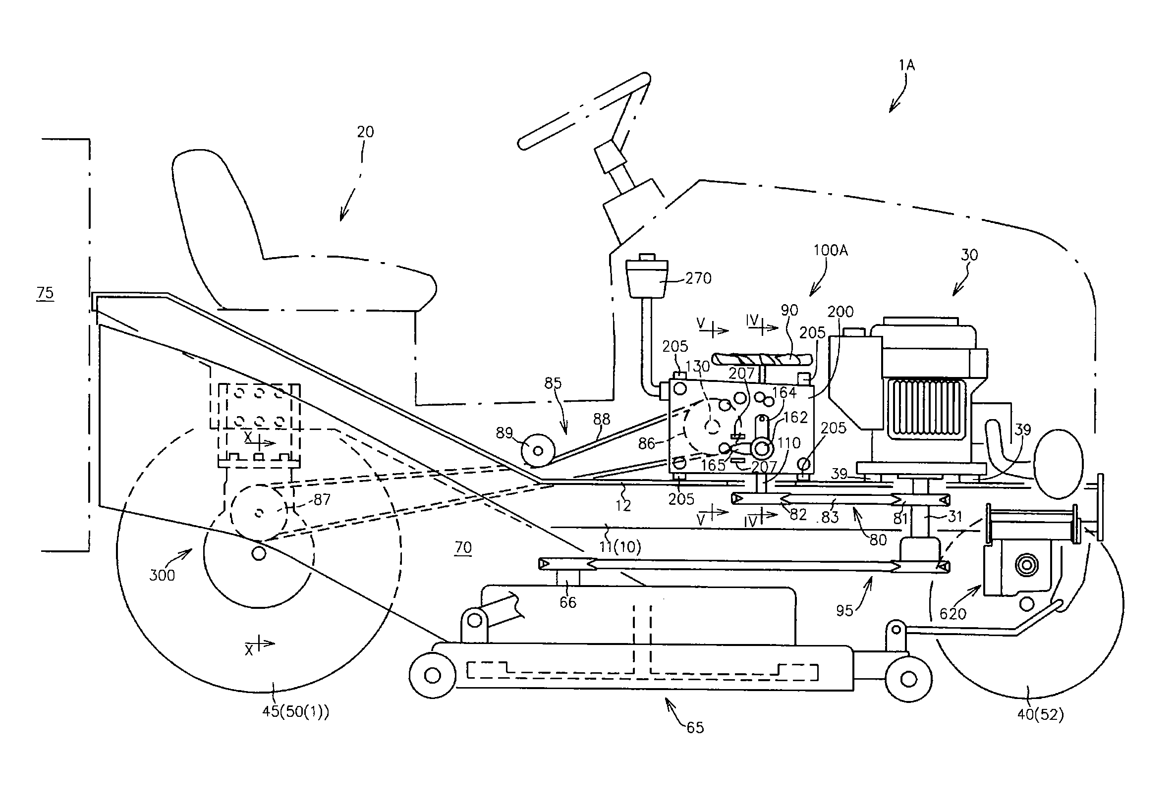
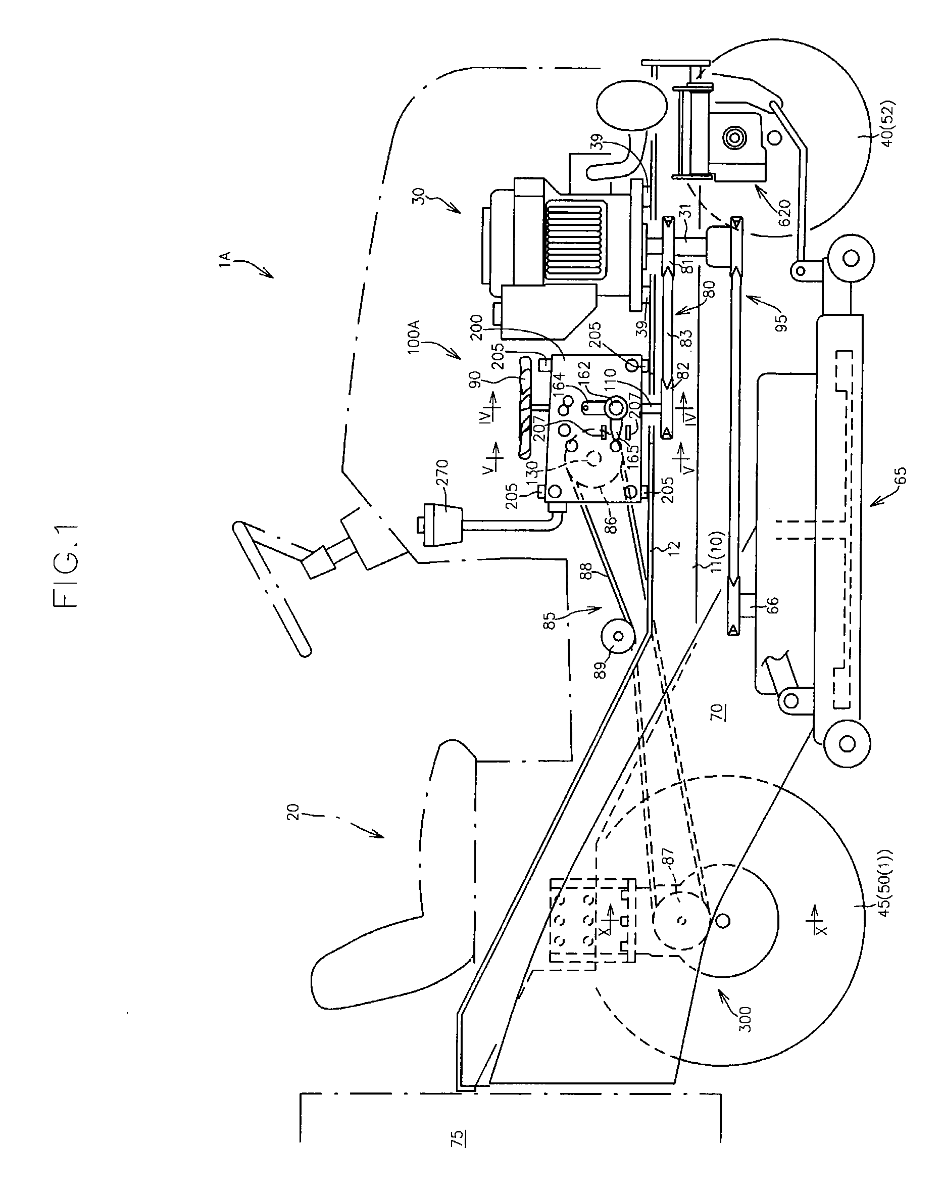
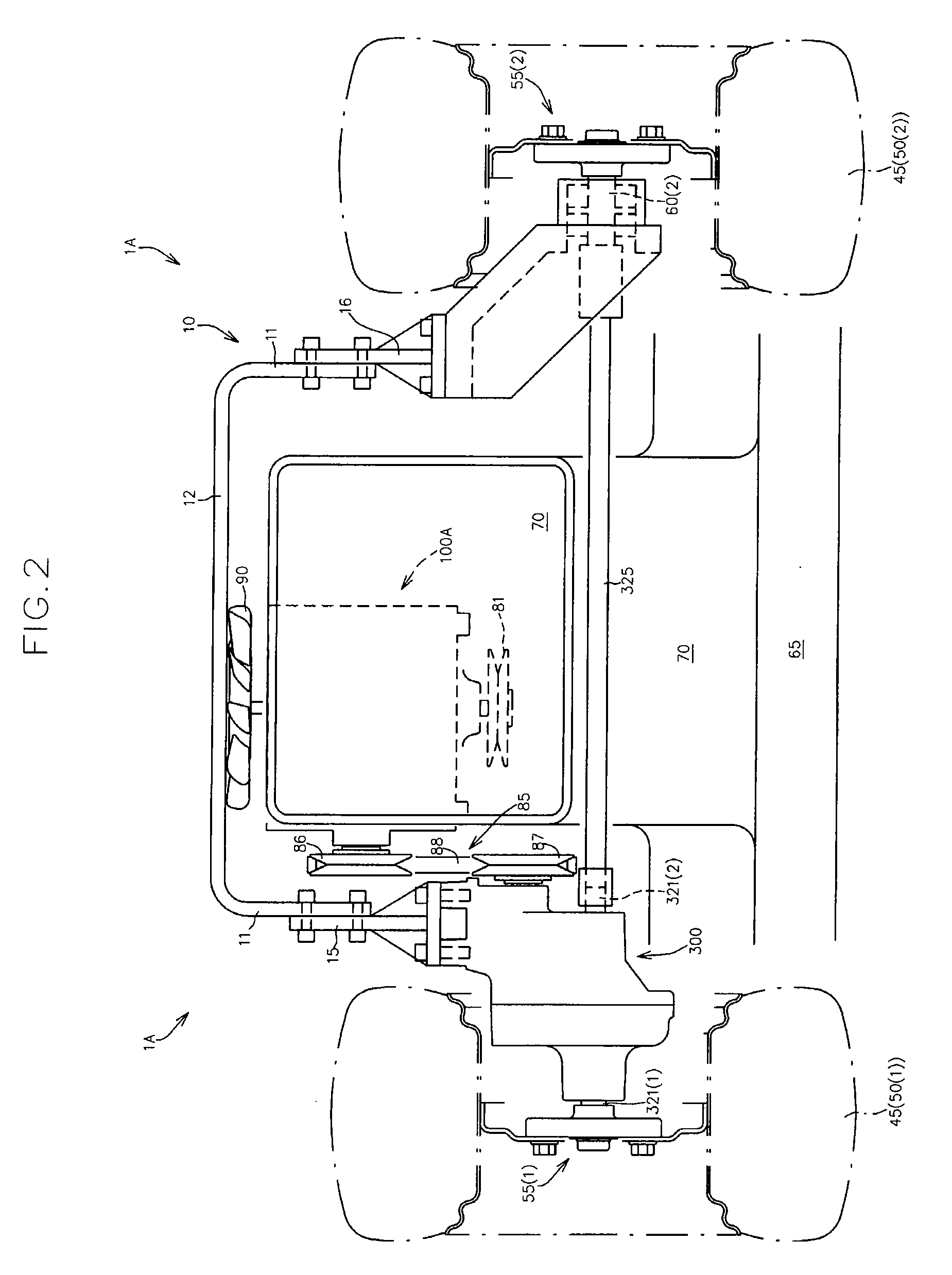
[0064]FIGS. 1 to 3 illustrate a side view, a rear view and a hydraulic circuit diagram of a working vehicle 1A according to the present embodiment, respectively.

[0065]As illustrated in FIG. 1 and FIG. 2, the working vehicle 1A is structured as a mid-mount mower tractor having a mower device 65 at the center in a vehicle lengthwise direction and a rear discharge duct 70 between a pair of main driving wheels 50(1) and 50(2).

[0066]More specifically, as illustrated in FIGS. 1 to 3, the working vehicle 1A includes a vehicle frame 10 including a pair of main frames 11 provided along the vehicle lengthwise direction, a driver's seat 20 supported on the vehicle frame 10, a driving power source 30 supported by the vehicle frame 10, a pair of left and right front wheels 40 which are placed on one side in the vehicle lengthwise direc...

second embodiment

[0294]Another embodiment of the HST unit according to the present invention will now be described with reference to the accompanying drawing.

[0295]FIG. 21 illustrates a vertical cross-sectional view of an HST unit 100D according to the present embodiment.

[0296]In the drawing, the same reference numerals are denoted for the same components as those of the first embodiment to omit the detailed explanation thereof.

[0297]As shown in FIG. 21, the HST unit 100D is different from the HST unit 100A in the first embodiment, in that the positions where the hydraulic pump main body 120 and the auxiliary pump main body 180 are mounted are changed.

[0298]Specifically, in the present embodiment, with the state, as a reference, where the HST unit 100D is mounted at the working vehicle 1A, the hydraulic pump main body 120 and the auxiliary pump main body 180 is positioned on the upper surface and the lower surface of a center section 150D, respectively.

[0299]More specifically, the HST unit 100D incl...

third embodiment

[0306]Still another embodiment of the HST unit according to the present invention will now be described with reference to the accompanying drawing.

[0307]FIG. 22 illustrates a horizontal cross-sectional view of an HST unit 100E according to the present embodiment.

[0308]In the drawing, the same reference numerals are denoted for the same components as those of the first and second embodiments to omit the detailed explanation thereof.

[0309]The HST unit 100E according to the present embodiment further includes a mechanical clutch mechanism 510 capable of being manually operated, in comparison with the HST unit in the first embodiment.

[0310]In the first embodiment, the motor shaft 130 has the first end 131 extending outward from the HST case 200 so that the motor shaft 130 functions as the HST output shaft 100b.

[0311]Instead of this configuration, in the HST unit 100E according to the present embodiment, the motor shaft 130 is entirely accommodated within the HST case 200, and there is ...


PUM


Abstract

The working vehicle includes an axle unit that has a differential gear device, an axle case, an axle input shaft and first and second main output shafts, and an HST unit that has a hydraulic pump main body, a hydraulic motor main body, a capacity adjustment mechanism, an HST case, a pump shaft and a motor shaft, an HST input shaft, and an HST output shaft, wherein the axle unit is directly or indirectly supported by the vehicle frame so as to be positioned close to a first main driving wheel in a state where the axle input shaft extends in a vehicle widthwise direction, wherein the HST unit is directly or indirectly supported by the vehicle frame at a position away from the axle unit in a state where the HST output shaft extends in the vehicle widthwise direction, and wherein the HST output shaft and the axle input shaft are operatively connected to each other through an endless type transmission member.

Description

BACKGROUND OF THE INVENTION[0001]1. Field of the Invention[0002]The present invention relates to a working vehicle configured so that rotational power whose speed has been changed in a non-stepwise manner by an HST is differentially transmitted to a pair of first and second driving wheels on left and right sides through a differential gear device.[0003]Further, the present invention relates to an HST unit including a hydraulic pump main body and a hydraulic motor main body.[0004]2. Background Art[0005]A travel-system transmission structure configured so that rotational power whose speed has been changed in a non-stepwise manner by an HST is differentially transmitted to a pair of main driving wheels through a differential gear device has been proposed and used in a working vehicle such as a tractor (refer to, for example, U.S. Pat. No. 6,993,906).[0006]However, the travel-system transmission structure described in the patent document has a problem of difficulty in providing a free s...

Claims


Application Information

Patent Timeline
Patent Type & Authority Applications(United States)
IPC IPC(8): B60K17/10F16D39/00F16D31/02
CPCB60Y2200/223B60K17/105
Inventor SUGIMOTO, HIROSHIKANENOBU, HIDEKIIWAKI, KOJISASHIKUMA, KENTA
Owner KANZAKI KOKYUKOKI MFG
Why Eureka
Try Eureka