
Air induction sound modification system for internal combustion engine

a technology of air induction sound and internal combustion engine, which is applied in the direction of machines/engines, combustion-air/fuel-air treatment, transportation and packaging, etc., can solve the problems of poor sound quality, creating a very odd appearance, and failing to adequately convey to the driver and passengers the engine's capabilities

Active Publication Date: 2009-09-24
FORD GLOBAL TECH LLC
View PDF16 Cites 8 Cited by
  • Summary
  • Abstract
  • Description
  • Claims
  • Application Information

AI Technical Summary

Benefits of technology

The present invention is an air induction sound modification system for an internal combustion engine. The system includes a multi-frequency sound suppression unit with a housing that has an air induction passage through it. The housing has Helmholtz resonators and a first expansion chamber with quarter wave resonators to suppress separate frequencies of undesirable sound. The central air induction passage enters the housing at an acute angle and exits with an offset to minimize flow losses. The system can suppress undesirable sounds with several different frequencies and create desirable sounds. The components of the system are housed within a single, compact housing.

Problems solved by technology

Needless to say, it is disadvantageous to install a powerful engine in a car or truck, only to have poor sound quality which fails to adequately convey to the driver and passengers the engine's capabilities.
However, such resonators were frequently branched from air induction pipes at odd locations, creating a very odd appearance, with structures which were difficult to package within the confines of the underhood environment of a vehicle.

Method used


Image

  • Air induction sound modification system for internal combustion engine
  • Air induction sound modification system for internal combustion engine
  • Air induction sound modification system for internal combustion engine

Examples


Embodiment Construction

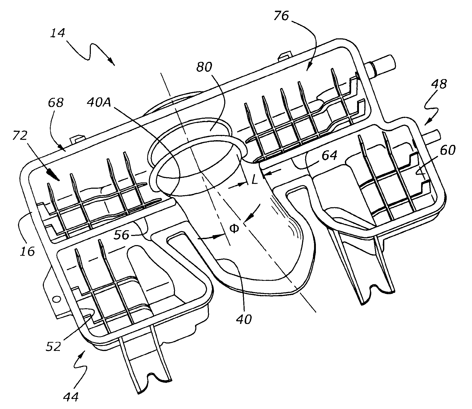
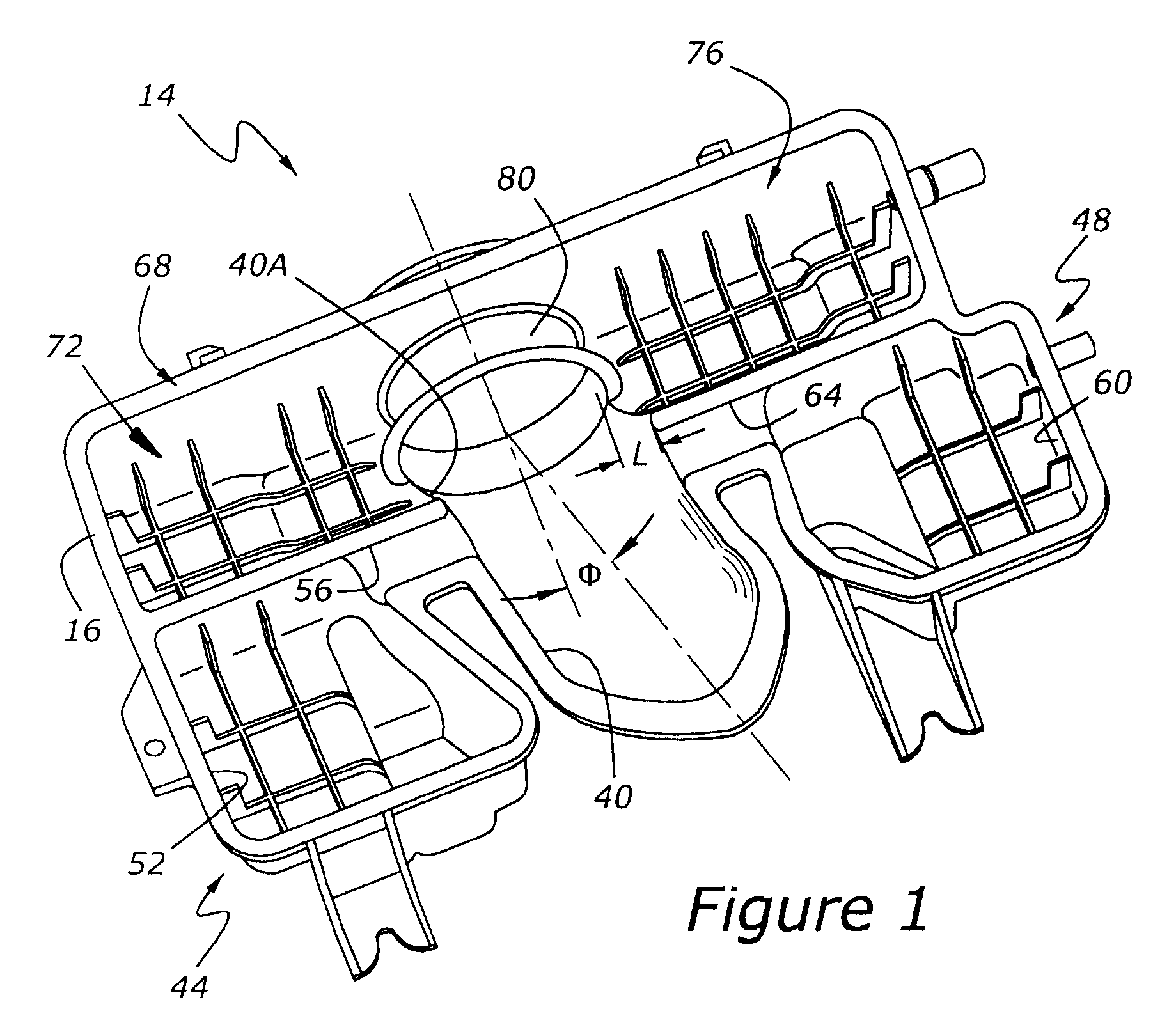
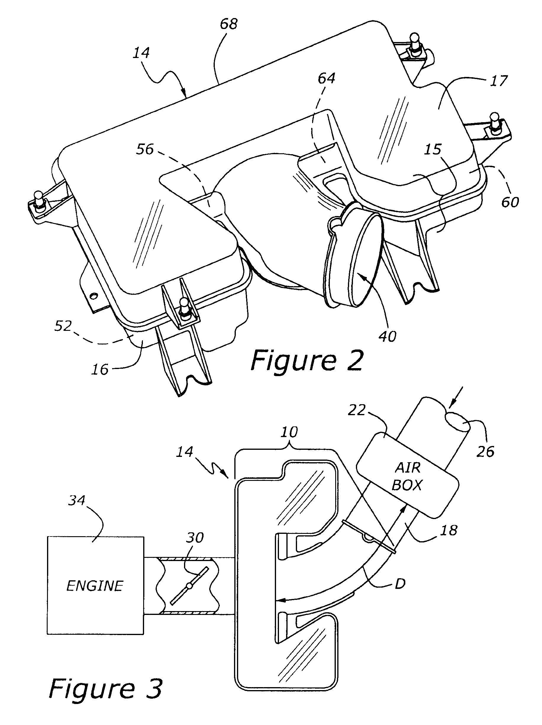
[0018]As shown in FIG. 3, an engine, 34, draws air through an air induction sound modification system, 10, which is mounted between a throttle body containing throttle plate, 30, and an expansion chamber which is the second of two expansion chambers in the system, and which functions as an air cleaner box. Air enters the engine's induction system through air inlet opening 26. Air induction sound modification system 10 includes at least two components: a multi-frequency sound suppression unit, 14, and a sound generator, 18, extending from second expansion chamber 22 to throttle plate 30. Multi-frequency sound suppression unit 14 functions to eliminate unwanted frequencies from the sound emitted by the air induction system. Sound generator 18, on the other hand, functions to emit sound at desirable frequencies. Accordingly, the present system is properly termed a “sound modification system” because it not only eliminates undesirable sound, but also amplifies and projects wanted sounds...


PUM


Abstract

An air induction sound modification system for an internal combustion engine includes a multi-frequency sound suppression unit having Helmholtz resonators and a multi-component expansion chamber. A sound generator, which functions to radiate sound at a desirable, tuned frequency, extends between the multi-function sound suppression unit and a second expansion chamber, such as an air cleaner box.

Description

CROSS REFERENCE TO RELATED APPLICATIONS[0001]None.BACKGROUND OF THE INVENTION[0002]1. Field of the Invention[0003]The present invention relates to a system for changing the sound output of an internal combustion engine air induction system by suppressing unwanted noise at selected frequencies and by increasing the emission of sound at desired, preselected frequencies.[0004]2. Related Art[0005]In the world of automotive internal combustion engines, psychoacoustics is important because the motorist's perception of a vehicle's roadworthiness is greatly influenced by the sound of the engine within a vehicle. In other words, motorists listen to their engine as an indication of not only the engine's health, but also the power output of the engine. Needless to say, it is disadvantageous to install a powerful engine in a car or truck, only to have poor sound quality which fails to adequately convey to the driver and passengers the engine's capabilities. And, in any event, it is desirable to...

Claims


Application Information

Patent Timeline
Patent Type & Authority Applications(United States)
IPC IPC(8): F02B77/13
CPCF02M35/1266F02M35/1261
Inventor ROSS, TONYDROSTE, STEVEHEHAR, HARWINDERARTEAGA, JOSE
Owner FORD GLOBAL TECH LLC
Learn More