Pixelated Scintillation Detector and Method of Making Same

Inactive Publication Date: 2009-09-24
SAINT GOBAIN CERAMICS & PLASTICS INC
View PDF22 Cites 22 Cited by
  • Summary
  • Abstract
  • Description
  • Claims
  • Application Information

AI Technical Summary

Benefits of technology

[0008]Consistent with a further aspect, is method is provided for detecting radiation. This method includes: providing a pixelated scintillation detector including a position sensitive photodetector and an array of crystal pixel elements mechanically and optically coupled directly to the position sensitive photodetector using an optical coupling material without a window; applying radiation to the array of crystal pixel elements; producing an output from the position sensitive photodetector in response to excitatory radiation; and processing the output from the position sensitive photodetector to produce detected radiation information corresponding to each of the pixel elements in the array of crystal pixel elements. The detected radiation information includes at least a flood image having an improved spatial resolution as compared to a flood image generated under the same conditions by a pixelated scintillation detector including an array of crystal pixel elements coupled to a po

Problems solved by technology

Cutting the crystal into pixels before the crystal is coupled to the PSPMT presents challenges, however, because assembling and coupling the crystal pixel elements is difficult.
The manufacturing of a pixelated scintillation detector also presents challenges because the crystals may have certain properties (e.g., hygroscopicity) that require handling the crystals in a certain way and because the PSPMT is susceptible to damage and should be protected.
Because some scintillation crystals are hygroscopic and fragile, the crystal must be cut under certain conditions to prevent damage to the crystal.
The optical window acts as a substrate for the crystal and allo

Method used


Image

  • Pixelated Scintillation Detector and Method of Making Same
  • Pixelated Scintillation Detector and Method of Making Same
  • Pixelated Scintillation Detector and Method of Making Same

Examples


Embodiment Construction

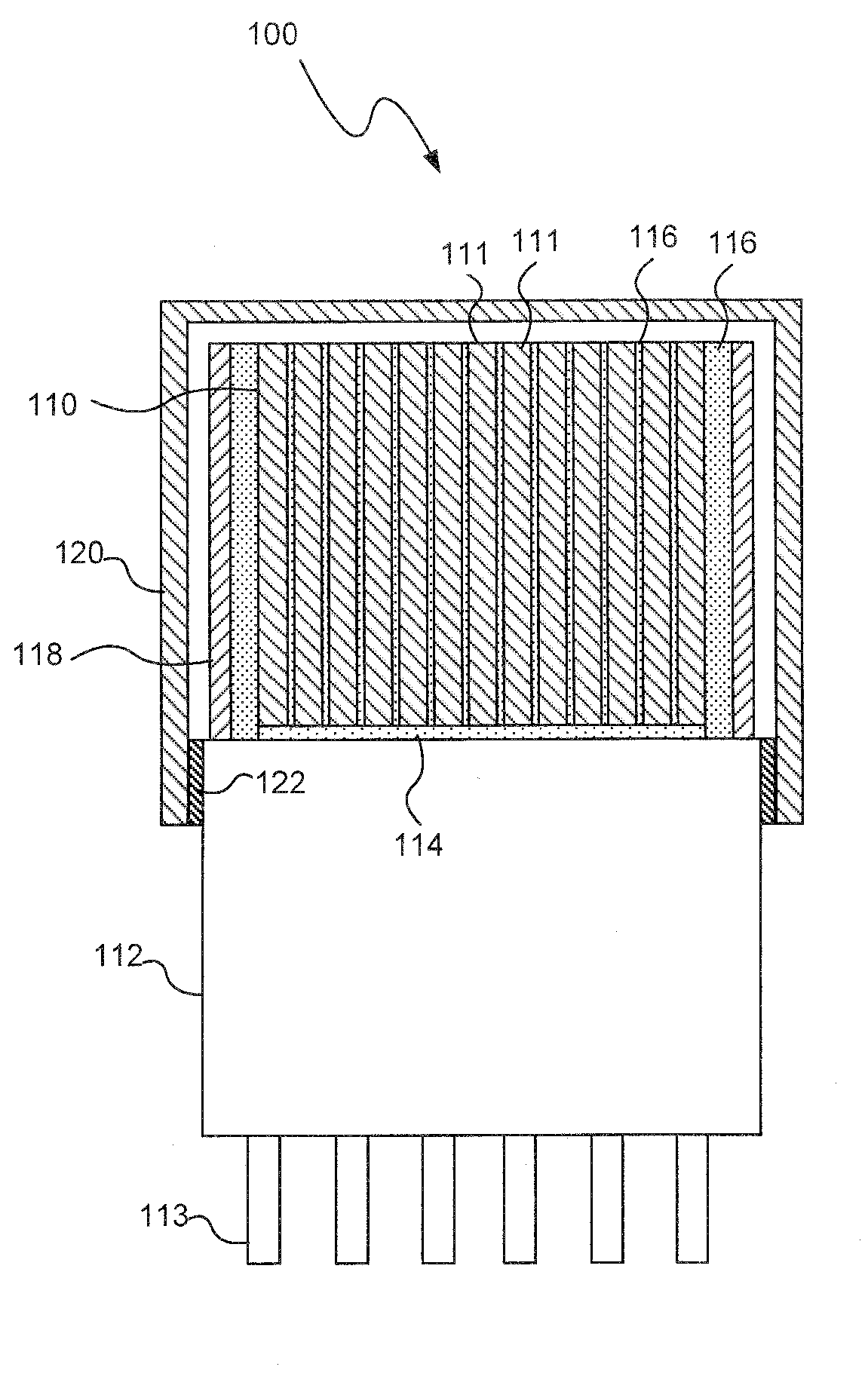
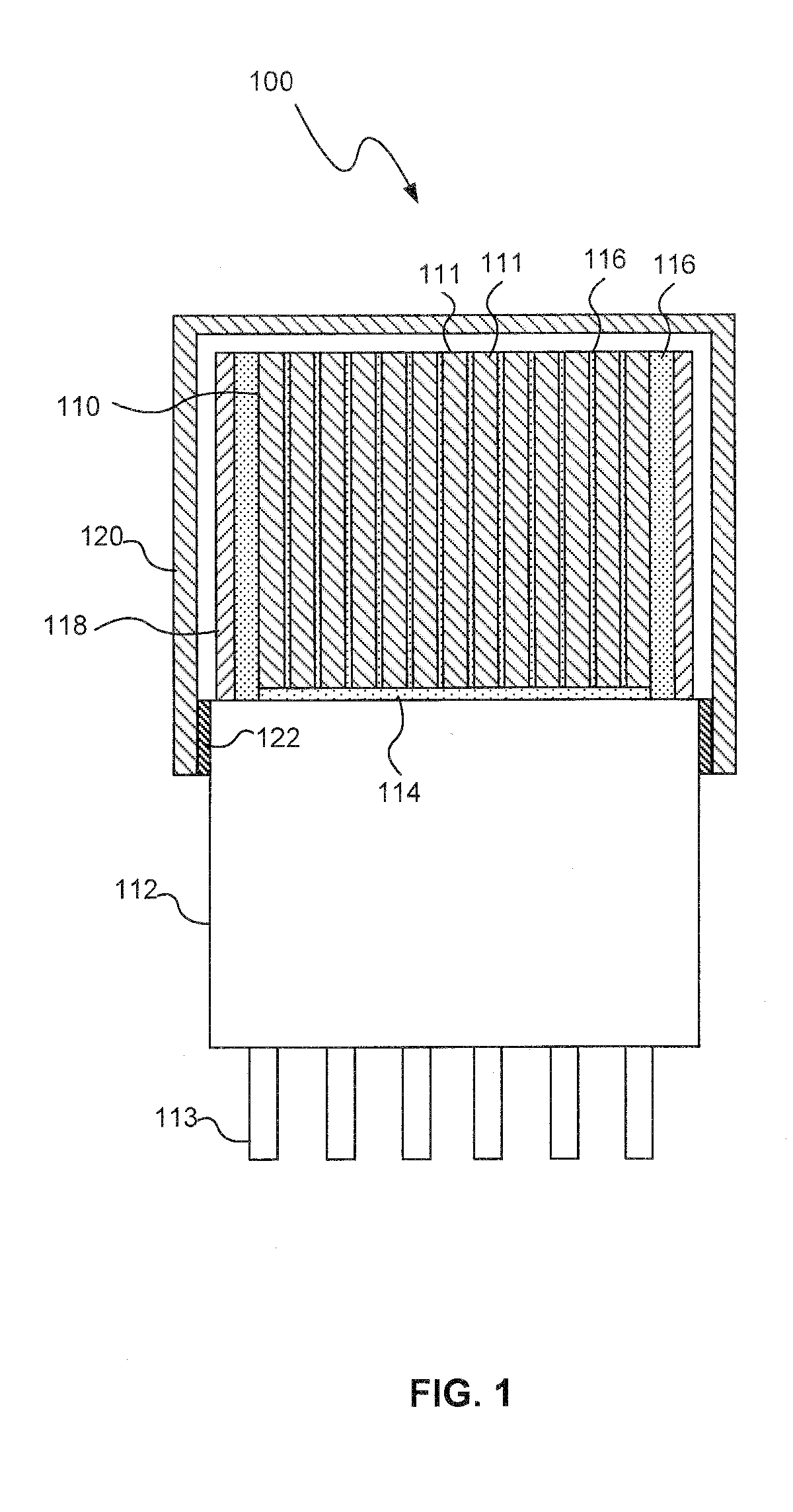
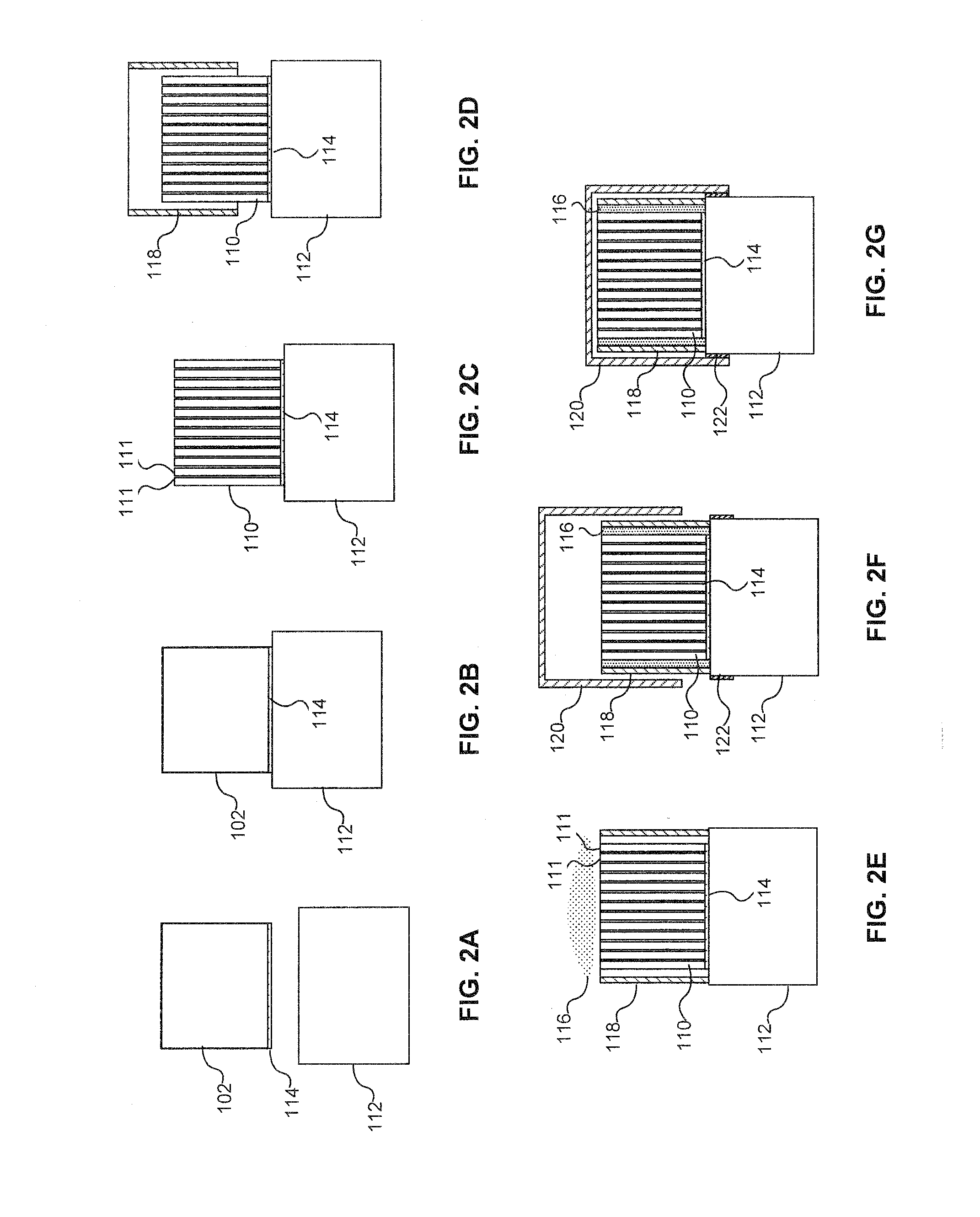
[0025]In general, a pixelated scintillation detector, consistent with embodiments described herein, includes a pixelated scintillation crystal mechanically and optically coupled to a position sensitive photodetector. The pixelated scintillation crystal may be coupled to the position sensitive photodetector without using a window between the crystal and photodetector. According to one method of constructing the scintillation detector, a solid scintillation crystal may be coupled to the position sensitive photodetector and cut while coupled to the photodetector to form the pixelated scintillation crystal.

[0026]As used herein, the term “radiation” includes electromagnetic radiation and high-energy particles (e.g., gamma radiation, alpha particles and beta particles). The term “light” includes electromagnetic radiation of any wavelength and is not limited to visible light. The term “scintillation crystal” refers to a crystal material that emits light (“scintillation light”) in response ...


PUM


Abstract

A scintillation detector may include a pixelated scintillation crystal mechanically and optically coupled to a position sensitive photodetector, such as a position sensitive photomultiplier tube (PSPMT). The pixelated scintillation crystal may be coupled to the position sensitive photodetector without using a window between the crystal and photodetector. According to one method of constructing the scintillation detector, a solid scintillation crystal may be coupled to the position sensitive photodetector and cut while coupled to the photodetector to form the pixelated scintillation crystal.

Description

CROSS-REFERENCE TO RELATED APPLICATIONS[0001]The present application claims the benefit of U.S. Provisional Application Ser. No. 61 / 037,473 filed on Mar. 18, 2008, which is fully incorporated herein by reference.TECHNICAL FIELD[0002]The present invention relates to radiation detectors and more particularly, to a pixelated scintillation detector and method of making same.BACKGROUND INFORMATION[0003]Scintillation detectors are generally used to detect radiation that is not easily detected by conventional photodetectors. A scintillator or scintillation crystal absorbs the radiation and converts the energy of the radiation to a light pulse. The light may be converted to electrons (i.e., an electron current) in a photomultiplier tube, which amplifies the electron current. Scintillation detectors may be used in various industries and applications including medical (e.g., to produce images of internal organs), geophysical (e.g., to measure radioactivity of the earth), inspection (e.g., non...

Claims


Application Information

Patent Timeline
IPC IPC(8): G01T1/20H01L21/00
CPCH01L31/02322G01T1/2018G01T1/20183G01T1/20187
Inventor SELFE, THOMAS A.HERR, DANIEL J.MENGE, PETER R.
Owner SAINT GOBAIN CERAMICS & PLASTICS INC
Why Eureka
Try Eureka