Electro-optical display, electrophoretic display, and electronic device

Active Publication Date: 2009-09-24
E INK CORPORATION
View PDF0 Cites 34 Cited by
  • Summary
  • Abstract
  • Description
  • Claims
  • Application Information

AI Technical Summary

Benefits of technology

[0019]An advantage of some aspects of the invention is to provide an electro-optical display, an

Problems solved by technology

However, when the films instead of glass substrates are used as the two substrates holding the microcapsules therebetween, a problem of deterioration of the electrophoretic display due to infiltration of moisture occurs.
However, in the case of the films, it is difficult to maintain such effect high.
When an electrophoretic display configured using the films is exposed to high temperature and high humidity for a long period of time, deterioration is caused by infiltration of moisture, resulting in a significant decrease in display quality.
In particular, when the display may be used in outdoor environment, deterioration due to changes in temperature and humidity is concerned.
However, even in the above-mentioned technology, for example, under the environment of a hi

Method used


Image

  • Electro-optical display, electrophoretic display, and electronic device
  • Electro-optical display, electrophoretic display, and electronic device
  • Electro-optical display, electrophoretic display, and electronic device

Examples


embodiment 1

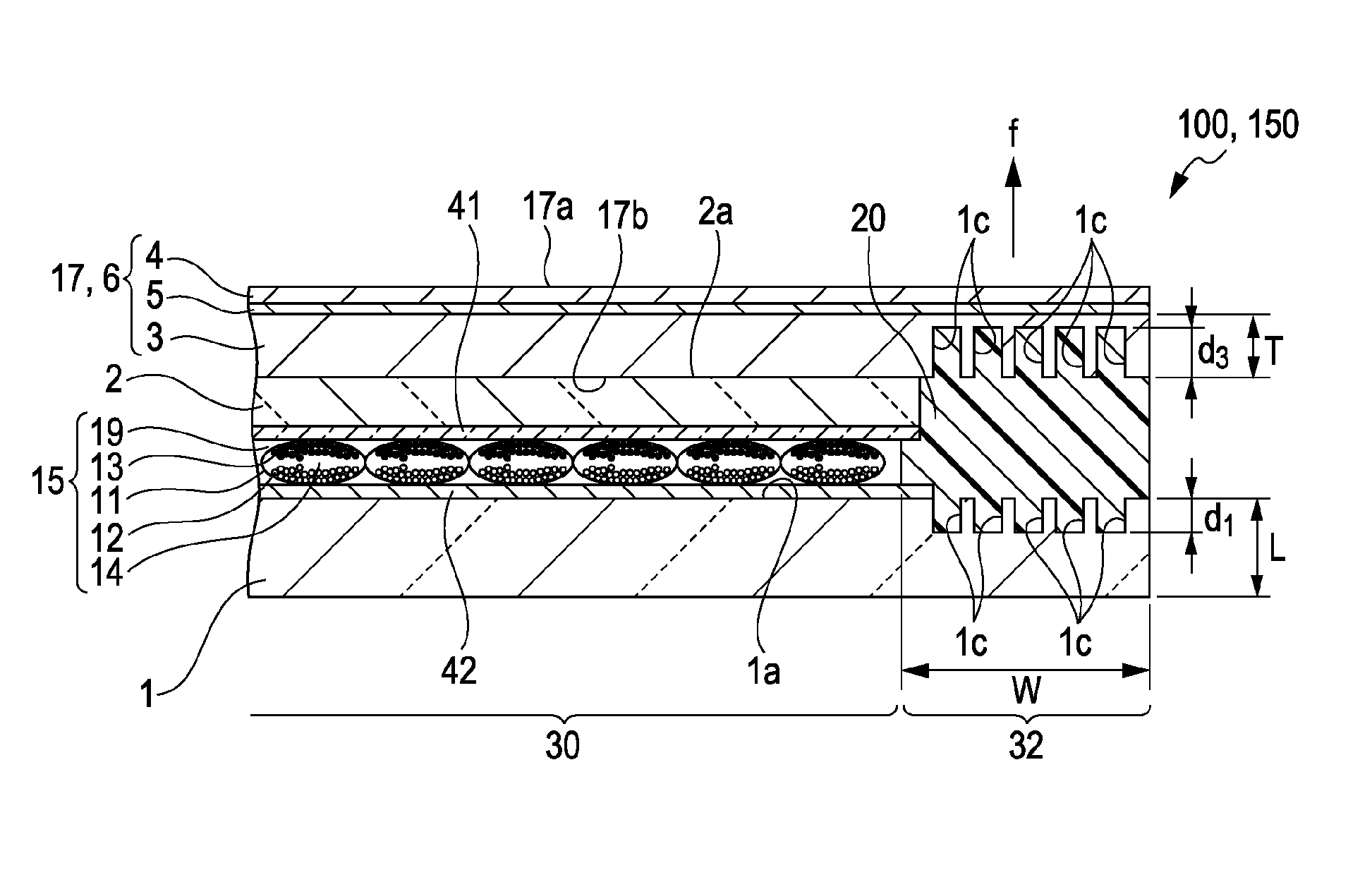
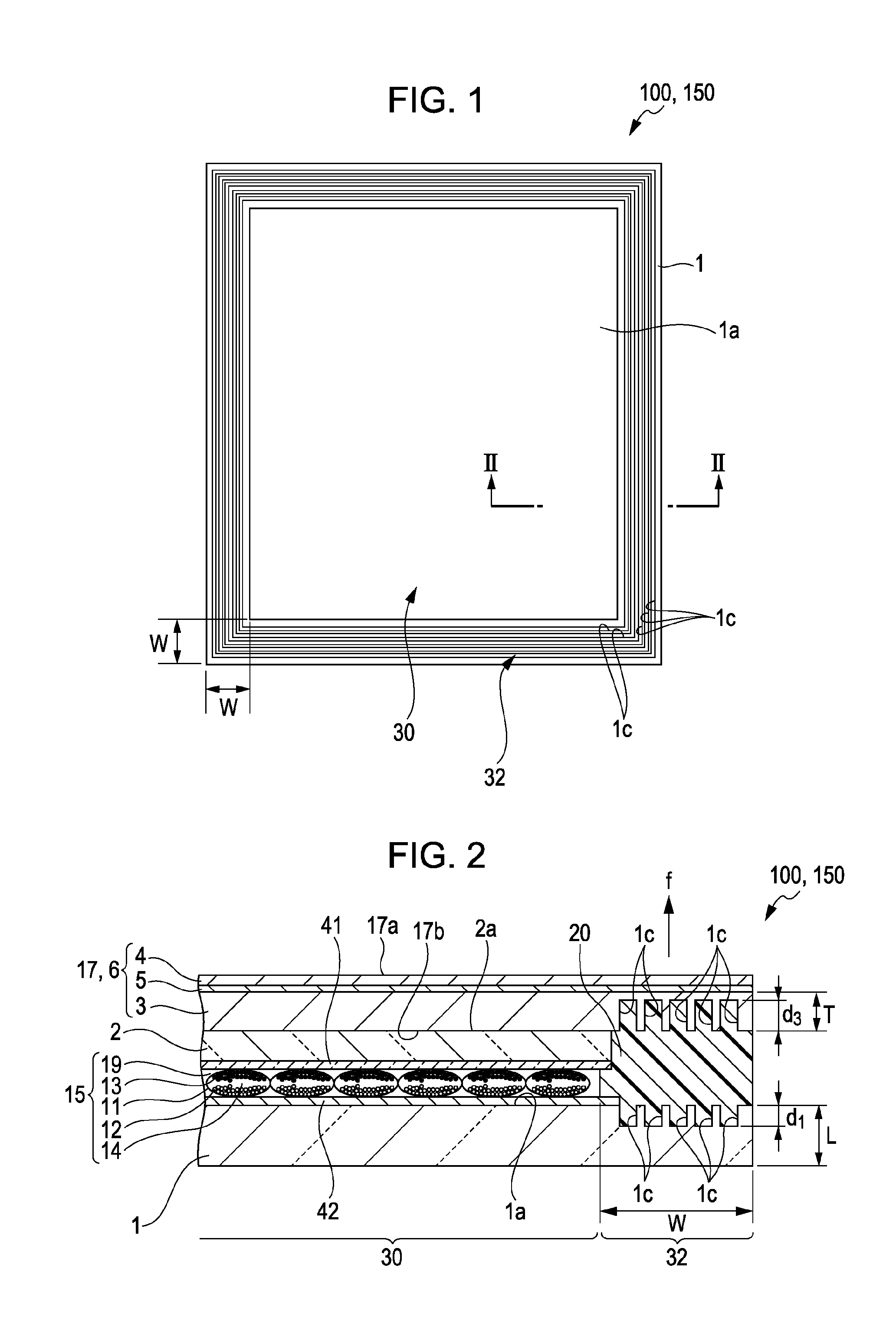
[0058]An electro-optical display 150 according to an embodiment of the invention will be described with referring to an electrophoretic display 100.

[0059]FIGS. 1 and 2 are drawings illustrating an example of the electrophoretic display 100, which is an embodiment of the invention. FIG. 1 is a plan view, and FIG. 2 is a cross-sectional view taken along the line II-II in FIG. 1.

[0060]As shown in FIG. 1, the electrophoretic display 100 according to the embodiment of the invention is roughly configured to include a display face (display region) 30 having an approximately rectangular shape where an electrophoretic layer (display layer) 15 is disposed on a surface 1a of a first substrate 1 and a sealing region 32 surrounding the display face (display region) 30. The sealing width of the sealing region is defined as W.

[0061]In the sealing region 32, the surface 1a of the first substrate 1 is provided with a plurality of grooves 1c so as to surround the display face (display region) 30.

[006...

embodiment 2

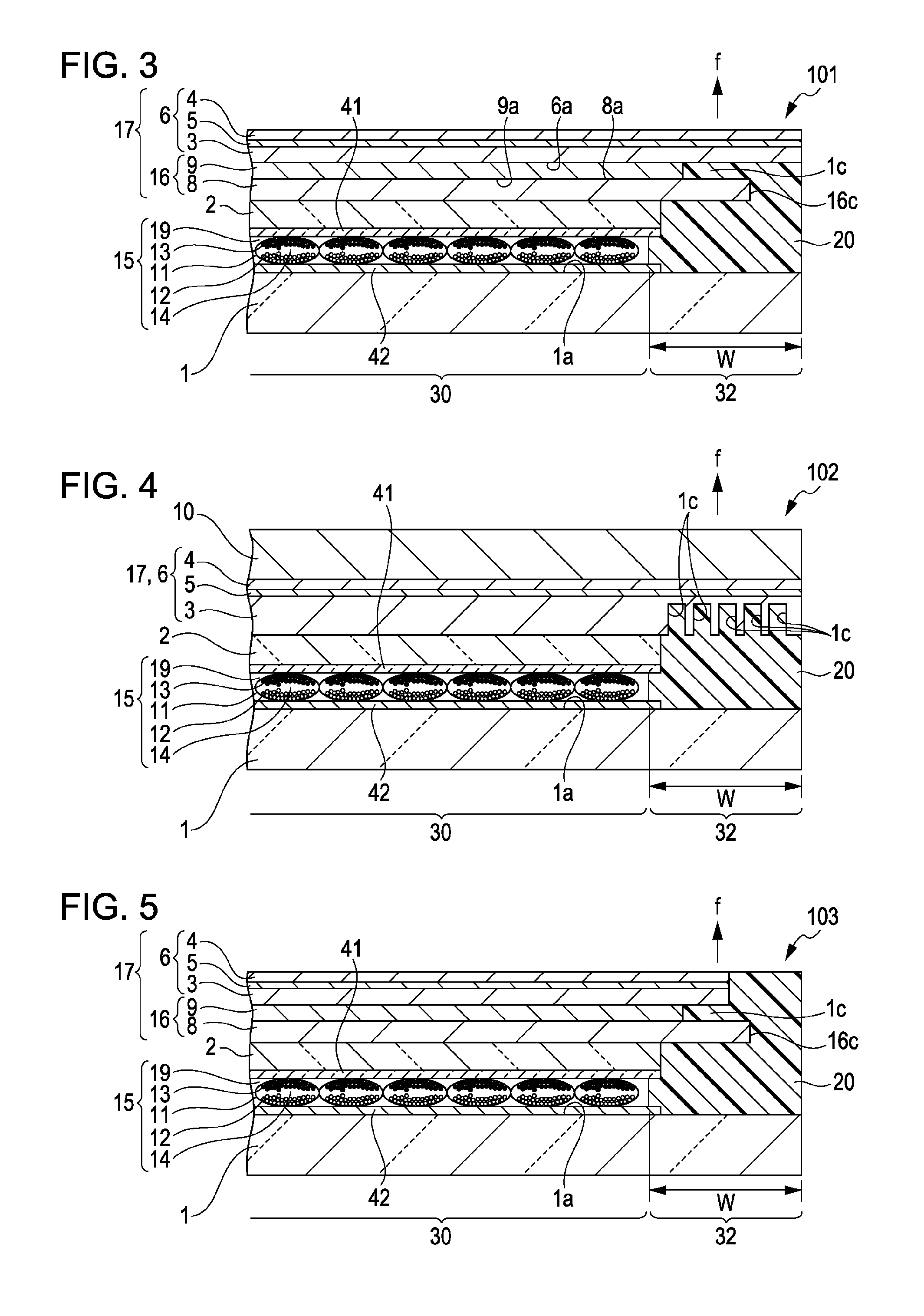
[0119]FIG. 3 is a cross-sectional view illustrating another electrophoretic display according to an embodiment of the invention.

[0120]The electrophoretic display 101 according to this embodiment of the invention is configured to be the same as that in Embodiment 1 except that the groove 1c is provided in the side face of the cover layer 17.

[0121]The cover layer 17 is disposed on the surface 2a of the second substrate 2 on the opposite side of the display layer and is configured from a transparent moisture-proof sheet 6 and a moisture-proof subsidiary sheet 16. The transparent moisture-proof sheet 6 is composed of a laminate of a plurality of moisture-proof bases 3 and 4 and an inorganic material layer 5 disposed between the moisture-proof bases 3 and 4 at least such that the inorganic material layer 5 is in contact with the moisture-proof base 4 on the uppermost side, and the moisture-proof subsidiary sheet 16 is composed of moisture-proof bases 8 and 9. The thus provided cover laye...

embodiment 3

[0128]FIG. 4 is a cross-sectional view illustrating another electrophoretic display according to an embodiment of the invention.

[0129]The electrophoretic display 102 according to this embodiment of the invention is configured to be the same as that in Embodiment 1 except that the grooves 1c are provided only in a surface 17b on the display layer side of the cover layer 17, and the other surface 17a of the cover layer 17 on the opposite side of the display layer is bonded to a surface protection sheet 10.

[0130]The surface protection sheet 10 is not particularly limited as long as it is a transparent material that can exhibit a surface protection effect without hindering image display, and is preferably a resin film having flexibility. Examples of the material include various resins, for example, cellulose resins such as triacetyl cellulose (TAC), polyester resins such as polyethylene terephthalate (PET) and polyethylene naphthalate (PEN), polyethylene (PE) resins, polystyrene (PS) re...


PUM


Abstract

An electro-optical display includes a first substrate and a second substrate opposing to each other, a display layer disposed between the first substrate and the second substrate, and a cover layer covering a surface of the second substrate on an opposite side of the display layer. A surface of the display layer disposed on the first substrate is a display face, and the first substrate and the cover layer are bonded with a moisture-proof resin disposed at a sealing region surrounding the display face. The first substrate and/or the cover layer have a groove in the surface that is in contact with the moisture-proof resin, and the groove is filled with the moisture-proof resin.

Description

BACKGROUND[0001]1. Technical Field[0002]The present invention relates to an electro-optical display, an electrophoretic display, and an electronic device.[0003]2. Related Art[0004]Flat electro-optical displays represented by liquid crystal displays are utilized in various electronic devices, such as OA equipment, information terminals, clocks, and televisions, by taking advantage of the characteristics such as thin profile, lightness in weight, and low power consumption.[0005]Recently, as the electro-optical displays having such characteristics, electrophoretic displays (EPDs) have been remarkably developed. Among the electrophoretic displays, in particular, film-like displays have character visibility and flexibility similar to those of paper media and are therefore known as electronic papers.[0006]A microcapsule-type electrophoretic display (microcapsule-type EPD) is a typical electrophoretic display.[0007]In the microcapsule-type electrophoretic display, microcapsules containing ...

Claims


Application Information

Patent Timeline
IPC IPC(8): G02F1/167G02F1/01G02F1/16755G02F1/16757G02F1/1679
CPCG02F1/1339G02F1/167G02F2201/503G02F2201/50G02F2001/133311G02F1/16755G02F1/16757G02F1/1679G02F1/133311
Inventor ITO, WATARUYUZAWA, HIKARI
Owner E INK CORPORATION
Why Eureka
Try Eureka