Binoculars with micromirror array lenses

a technology of micromirror array and binoculars, which is applied in the field of binoculars, can solve the problems of poor image quality, wear and tear, and adversely affect the portability of binoculars, and achieve the effects of low cost, light weight and high image quality of binoculars

Active Publication Date: 2009-09-24
STEREO DISPLAY
View PDF101 Cites 10 Cited by
  • Summary
  • Abstract
  • Description
  • Claims
  • Application Information

AI Technical Summary

Benefits of technology

[0005]The present invention addresses the problems of the prior art and provides binoculars with Micromirror Array Lenses, which are capable of providing focusing and / or zoom functions without or with minimal macroscopic mechanical lens movement. Also, the present invention provides low cost, light weight, and high image quality binoculars.
[0009]The micromirrors in the Micromirror Array Lens are controlled electrostatically or electromagnetically, wherein the micromirrors can be controlled individually or in group. Each micromirror can have up to three degrees of freedom motion including two degrees of freedom rotational motion and one degree of freedom translational motion. Since the micromirrors in the Micromirror Array Lens can have a plurality of motions, the Micromirror Array Lens can form a plurality of optical surface profiles. The Micromirror Array Lens can change its focal length, field of view, or optical axis by changing its optical surface profile. Therefore, the Micromirror Array Lens is a variable focusing lens having a variable optical property. Also, the Micromirror Array Lens is an adaptive optical component which compensates the aberration of the optical unit. The Micromirror Array Lens comprising micromirrors has a variable optical property, a very fast response time, a large focal length variation, a high optical focusing efficiency, a simple focusing structure, low power consumption, and a low production cost thanks to a mass production advantage.
[0013]Since the Micromirror Array Lens is capable of reproducing virtually any reflective optical surface by controlling the motions of the micromirrors, the Micromirror Array Lens makes the focus and / or the magnification of the binoculars changed by changing its optical surface profile without macroscopic mechanical lens movement.

Problems solved by technology

However, the repeated macroscopic mechanical lens movement can cause wear and tear and misalignment problems.
Also, the moving mechanism and multiple prisms can add significant weight to the binoculars which may adversely affect to their portability.
Binoculars having zoom function have not been used widely because they require complicated macroscopic mechanical lens movement and precise collimation of optical elements.
Also, the image quality of the conventional binoculars having zoom function is inferior to that of fixed magnification binoculars because it is very difficult to correct the optical aberration of the binoculars throughout an entire zoom range.
Therefore, the conventional binoculars having zoom function tend to be bulky, fragile, and expensive with inferior image quality, which are undesirable especially for outdoor use.

Method used


Image

  • Binoculars with micromirror array lenses
  • Binoculars with micromirror array lenses
  • Binoculars with micromirror array lenses

Examples


Embodiment Construction

[0056]The present invention will now be described in detail with reference to embodiments thereof as illustrated in the accompanying drawings. In the following description, numerous specific details are set forth in order to provide a thorough understanding of the present invention. It will be apparent, however, to one skilled in the art, that the present invention may be practiced without some or all of these specific details. In other instances, well known process steps and / or structures have not been described in detail in order to not unnecessarily obscure the present invention.

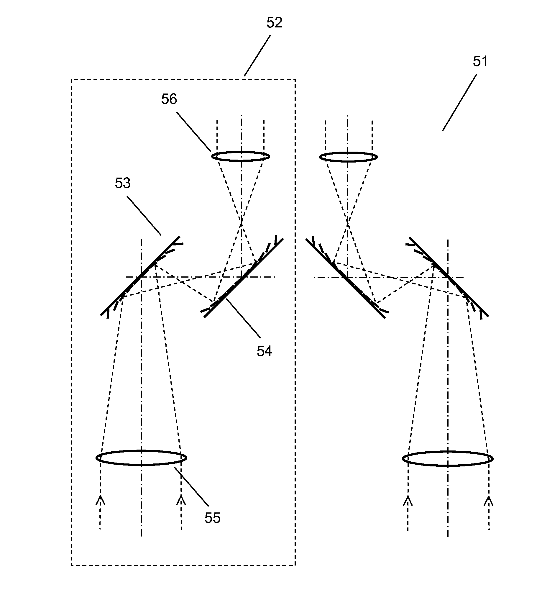
[0057]A pair of binoculars provides three-dimensional magnified images using two optical units. These two optical units are configured to provide images formed from at slightly different angles so that a viewer can see a three-dimensional image. The binoculars typically have focusing function to accommodate changes in distance between an object and the binoculars. In addition, the binoculars can have zoom...


PUM


Abstract

The binoculars of the present invention comprise two optical units; one optical unit for each eye. Each optical unit comprises a first reflective lens element and a second reflective lens element, wherein at least one of the reflective lens elements is a Micromirror Array Lens. The binoculars of the present invention provide focusing and / or zoom functions without or with minimal macroscopic mechanical lens movement.

Description

FIELD OF THE INVENTION[0001]The present invention relates to binoculars in general, and more specifically to the binoculars with Micromirror Array Lenses.BACKGROUND OF THE INVENTION[0002]A pair of binoculars provides three-dimensional magnified images using two parallel mirror-symmetric optical units. In the conventional binoculars, each optical unit comprises an objective lens group, a prism lens group, and an ocular lens group. The objective lens group gathers incident light from an object. The prism lens group typically comprising two prisms is configured to change and fold the path of light and provide an upright image. The ocular lens group magnifies the image formed by the objective lens group and the prism lens group. As the object distance is changed, the focus of the binoculars should be adjusted unless the optical units have a long depth of field. In the conventional binoculars, the distance between the objective lens group and the ocular lens group is configured to be adj...

Claims


Application Information

Patent Timeline
Patent Type & Authority Applications(United States)
IPC IPC(8): G02B23/02G02B5/09
CPCG02B23/02G02B26/0833G02B23/12G02B23/00G02B5/08
Inventor KIM, HYE YOUNGSOHN, JIN YOUNGCHO, GYOUNG ILSEO, CHEONG SOO
Owner STEREO DISPLAY
Why Eureka
Try Eureka