Optical Disc Recording Device, Method for Recording Data Onto Optical Disc, and Optical Disc

a recording device and optical disc technology, applied in the field of optical disc recording devices, methods for recording data onto optical discs, optical discs, etc., can solve the problems of difficult to suppress the distortion of marks at all linear velocities, difficult to raise the rise rate of laser beams, and difficult to suppress the distortion of marks in all linear velocities, so as to increase the capacity of next-generation optical discs, further suppress the distortion of marks, and enhance recording quality

Active Publication Date: 2009-09-24
PANASONIC CORP
View PDF11 Cites 0 Cited by
  • Summary
  • Abstract
  • Description
  • Claims
  • Application Information

AI Technical Summary

Benefits of technology

[0018]As discussed above, with the optical disk recording device and the data recording method thereof pertaining to the present invention, the distortion of marks can be further suppressed, and recording quality can be further enhanced, even when the optical disk includes a plurality of recording layers or when the linear velocity of the optical disk during recording is different from the optimal value specific to that optical disk. Therefore, the present invention is advantageous for further increasing the capacity of next-generation optical disks, and further increasing the speed of data recording.

Problems solved by technology

However, further raising the rise rate of the laser beam is not easily accomplished.
Nevertheless, when data is recorded by this technique on a multilayer disk including a plurality of recording layers, it has been difficult to suppress the distortion of marks in all of the recording layers because the heat radiation conditions vary from layer to layer.
Furthermore, when the linear velocity of the optical disk is changed during data recording with the above technique, it has been difficult to suppress the distortion of marks at all linear velocities because the heat characteristics of the recording layers vary with the linear velocity.
For instance, when the power of the laser beam is optimized during recording at a high linear velocity, it is impossible to avoid the expansion of a long mark in particular because the laser beam power becomes too high during recording at a low linear velocity.
Conversely, when the power of the laser beam is optimized during recording at a low linear velocity, the contraction of the shortest mark in particular cannot be avoided because the laser beam power becomes insufficient during recording at a high linear velocity.
This distortion of marks is a problem in that it impedes further improvement in recording quality.

Method used


Image

  • Optical Disc Recording Device, Method for Recording Data Onto Optical Disc, and Optical Disc
  • Optical Disc Recording Device, Method for Recording Data Onto Optical Disc, and Optical Disc
  • Optical Disc Recording Device, Method for Recording Data Onto Optical Disc, and Optical Disc

Examples


embodiment 1

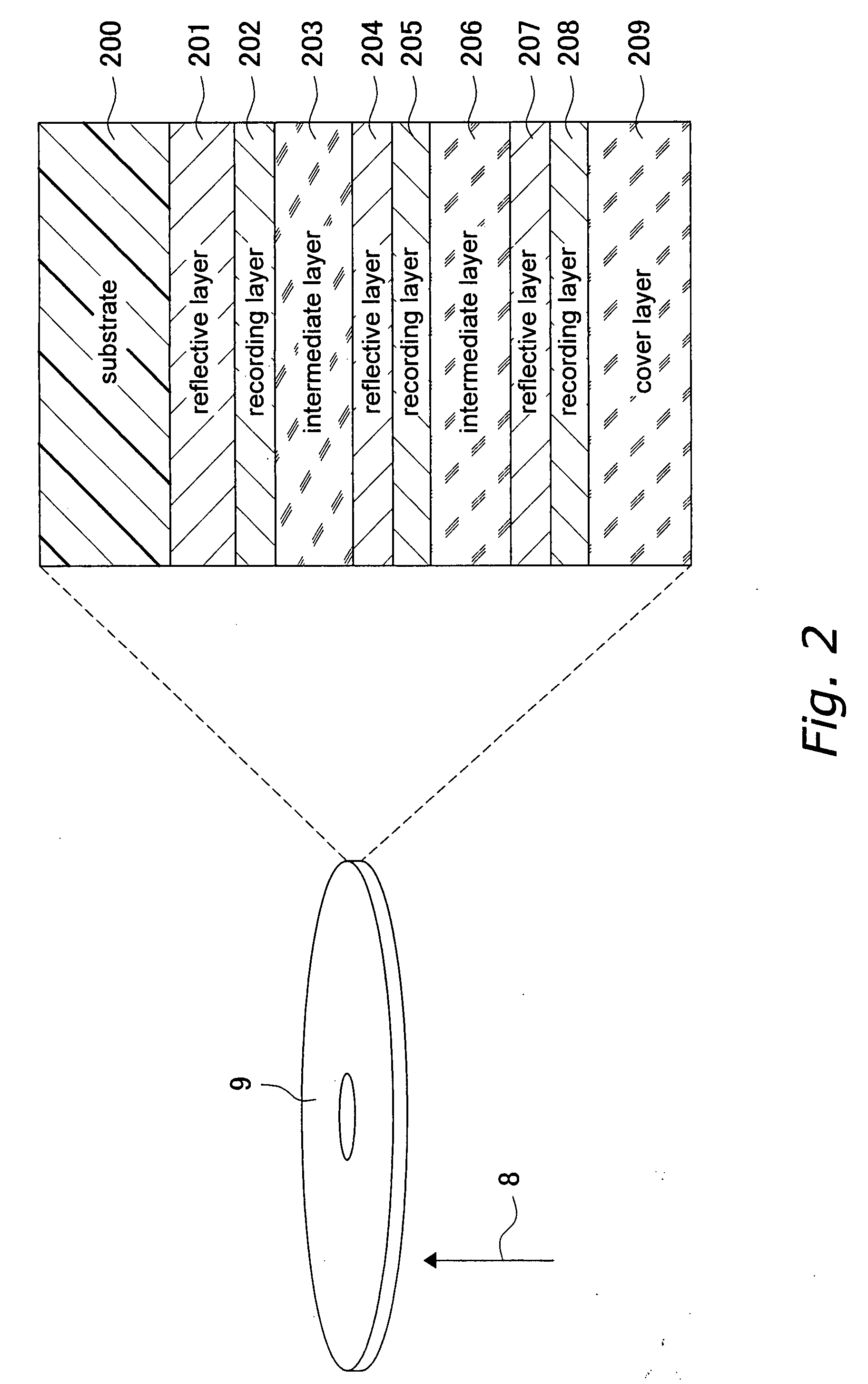
[0040]The method for recording data on an optical disk pertaining to Embodiment 1 of the present invention is utilized, for example, when the above-mentioned optical disk recording and reproduction device 1000 records data on either of the recording layer 202 closest to the substrate 200 (that is, deepest) and the middle recording layer 205 (see FIG. 2).

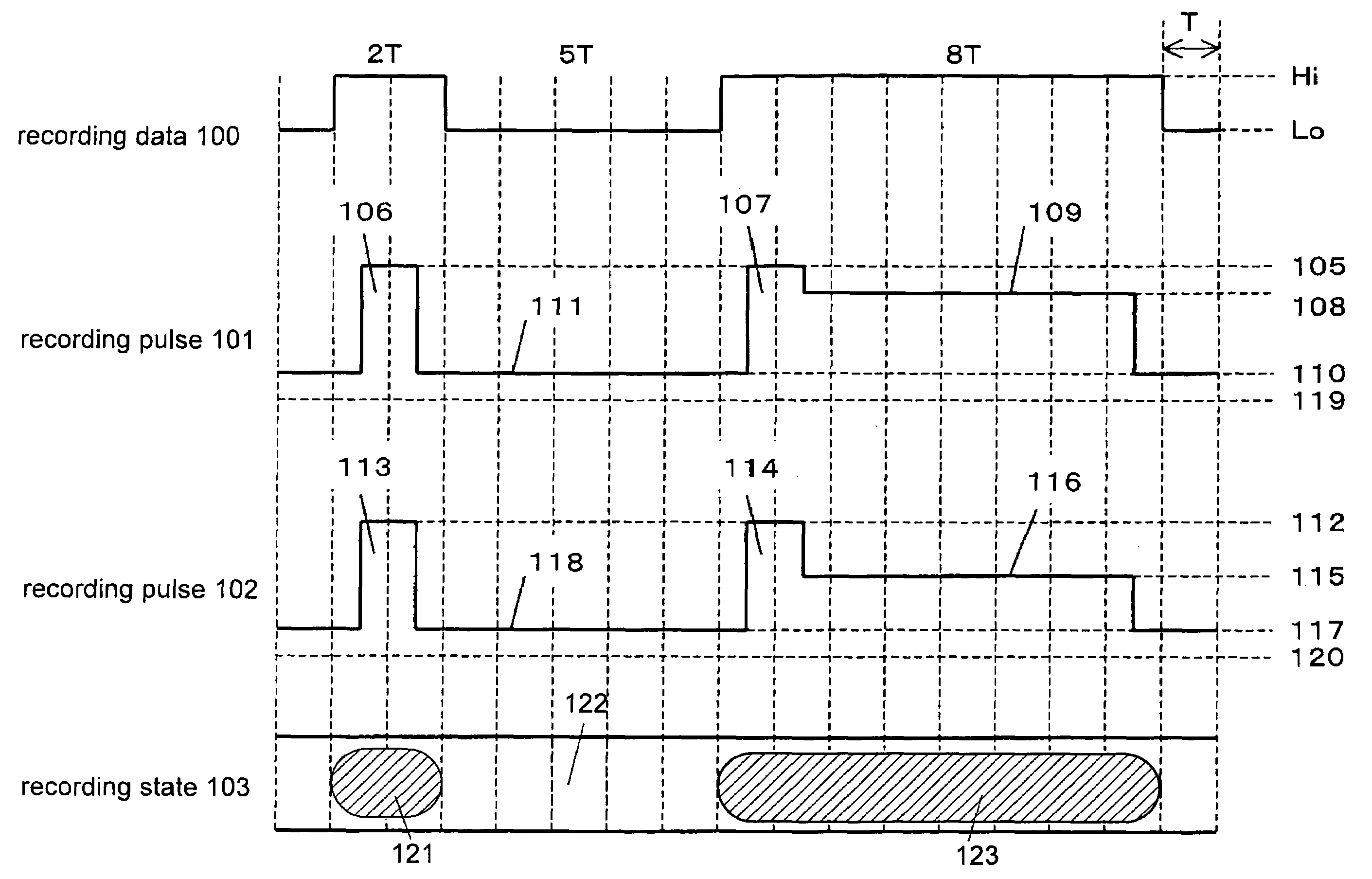
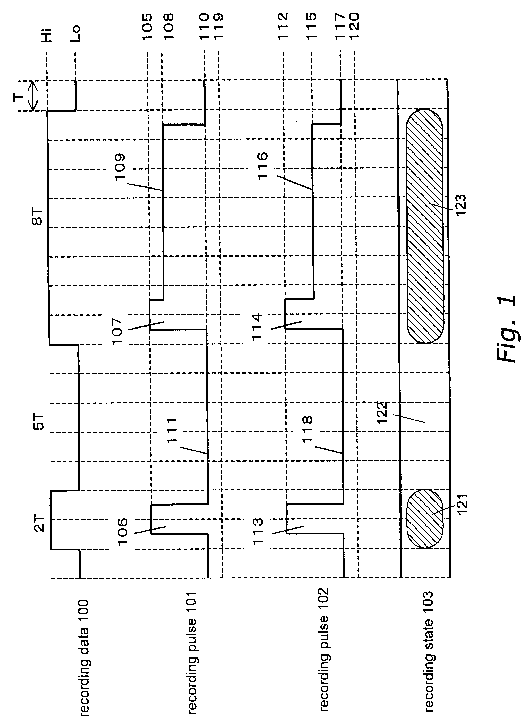
[0041]In FIG. 1, recording data 100 include a high-level (Hi) signal with a pulse width of 2T (2 times the recording clock period T), a low-level (Lo) signal with a pulse width of 5T, and a Hi signal with a pulse width of 8T, in that order. The Hi signal with a pulse width of 2T corresponds to the shortest mark 121 with a length of 2T, the Lo signal with a pulse width of 5T corresponds to a space 122 with a length of 5T, and the Hi signal with a pulse width of 8T corresponds to a long mark 123 with a length of 8T. When the recording data 100 is to be written on the deepest recording layer 202, the recording pulse production unit 4 pr...

embodiment 2

[0050]The method for recording data on an optical disk pertaining to Embodiment 2 of the present invention is utilized, for example, when the above-mentioned optical disk recording and reproduction device 1000 sets the recording speed (the linear velocity of the optical disk 9 during data recording) to its usual value (the optimal value specific to the optical disk 9 (such as a standard speed)), or to a higher value (such as a double speed), and records data on the middle recording layer 205 (see FIG. 2). Here, the optical disk recording and reproduction device 1000 reproduces the data recorded on the optical disk 9 at the usual speed (such as a standard speed).

[0051]For example, in FIG. 5, recording data 500 during recording at a standard speed includes a Hi signal with a pulse width of 2T (2 times the recording clock period T at a standard speed), a Lo signal with a pulse width of 5T, and a Hi signal with a pulse width of 8T, in that order. When the recording is performed at the s...

embodiment 3

[0058]Preferably, when the above-mentioned optical disk recording and reproduction device 1000 is mounted in a notebook PC or other such portable information device, the method for recording data on an optical disk pertaining to Embodiment 3 of the present invention is utilized. In this case, the optical disk recording and reproduction device 1000 sets the recording speed according to an operating state of the portable information device (whether or not it is connected to an AC power supply, the remaining battery charge, the quantity / priority of tasks being processed, and so forth). In particular, when it is necessary to lower power consumption, the recording speed is generally set lower than the optimal value specific to the optical disk 9. This lowers the laser power consumption (and particularly at the first recording power).

[0059]For example, in FIG. 6 the recording speed is set to a standard speed, and recording data 600 includes a Hi signal with a pulse width of 2T, a Lo signa...


PUM

PropertyMeasurementUnit
thicknessaaaaaaaaaa
thicknessaaaaaaaaaa
thicknessaaaaaaaaaa

Abstract

With the method of the present invention for recording data on an optical disk, a recording pulse corresponding to a long mark includes a combination of a leading pulse and a subsequent intermediate pulse. The level of the leading pulse indicates a first recording power, and the level of the intermediate pulse indicates a second recording power. When an optical disk includes a plurality of recording layers, the ratio of the second recording power to the first recording power is determined for each recording layer. When the recording speed is variable, the ratio of the second recording power to the first recording power is determined for each recording speed.

Description

TECHNICAL FIELD[0001]This invention relates to a device and method for recording data on a write-once or rewritable optical disk, particularly to recording power conditions used therein.BACKGROUND ART[0002]The Blu-ray Disc (BD; registered trademark) is known as a new standard for optical disks. With a BD, a standard-speed BD-RE has been gaining practical use in recent years as a rewritable type of optical disk. The one-side capacity of a BD-RE is 25 GB with a single layer, and 50 GB with two layers. A BD-R is also under development as a write-once type of optical disk.[0003]The following method for recording data on an optical disk was known for a conventional BD (see FIG. 11). The upper part in FIG. 11 is an example 900 of digital data (hereinafter referred to as recording data) to be recorded on an optical disk. The recording data 900 includes a high-level (Hi) signal with a pulse width of 2T (2 times the recording clock period T), a low-level (Lo) signal with a pulse width of 5T,...

Claims


Application Information

Patent Timeline
Patent Type & Authority Applications(United States)
IPC IPC(8): G11B7/00
CPCG11B7/00456G11B2007/0013G11B7/00736G11B7/0045G11B7/1263
Inventor FURUMIYA, SHIGERU
Owner PANASONIC CORP
Why Eureka
Try Eureka