Fuel cell cogeneration system, method of operating

a cogeneration system and fuel cell technology, applied in domestic hot water supply systems, heating types, sustainable manufacturing/processing, etc., can solve the problems of shortening the hot water storage means, consumers are incapable of consuming hot water, and hot water may run out with use, so as to inhibit hot water from running out and improve convenience

Inactive Publication Date: 2009-09-24
PANASONIC CORP
View PDF4 Cites 5 Cited by
  • Summary
  • Abstract
  • Description
  • Claims
  • Application Information

AI Technical Summary

Benefits of technology

[0009]The present invention has been directed to solving the above described problem, and an object of the present invention is to provide a fuel cell cogeneration system capable of inhibiting hot water from running out and of improving convenience.
[0015]The controller may increase the temperature of the fuel cell to the operating temperature by using a combination of the first temperature increasing operation and the second temperature increasing operation when the temperature of the external heat transfer medium is not lower than the detected ambient air temperature, and may increase the temperature of the fuel cell to the operating temperature mainly by the second temperature increasing operation when the temperature of the external heat transfer medium is lower than the detected ambient air temperature.

Problems solved by technology

However, since consumers typically consume hot water regardless of the amount of hot water remaining within the heat utilization means, the hot water may run out with use when the hot water stored in the heat utilization means is running short.
Especially when the heat utilization means is not internally equipped with a backup hot water supply device for ensuring the hot water, consumers are incapable of consuming the hot water.
This presents a serious inconvenience.

Method used


Image

  • Fuel cell cogeneration system, method of operating
  • Fuel cell cogeneration system, method of operating
  • Fuel cell cogeneration system, method of operating

Examples


embodiment 1

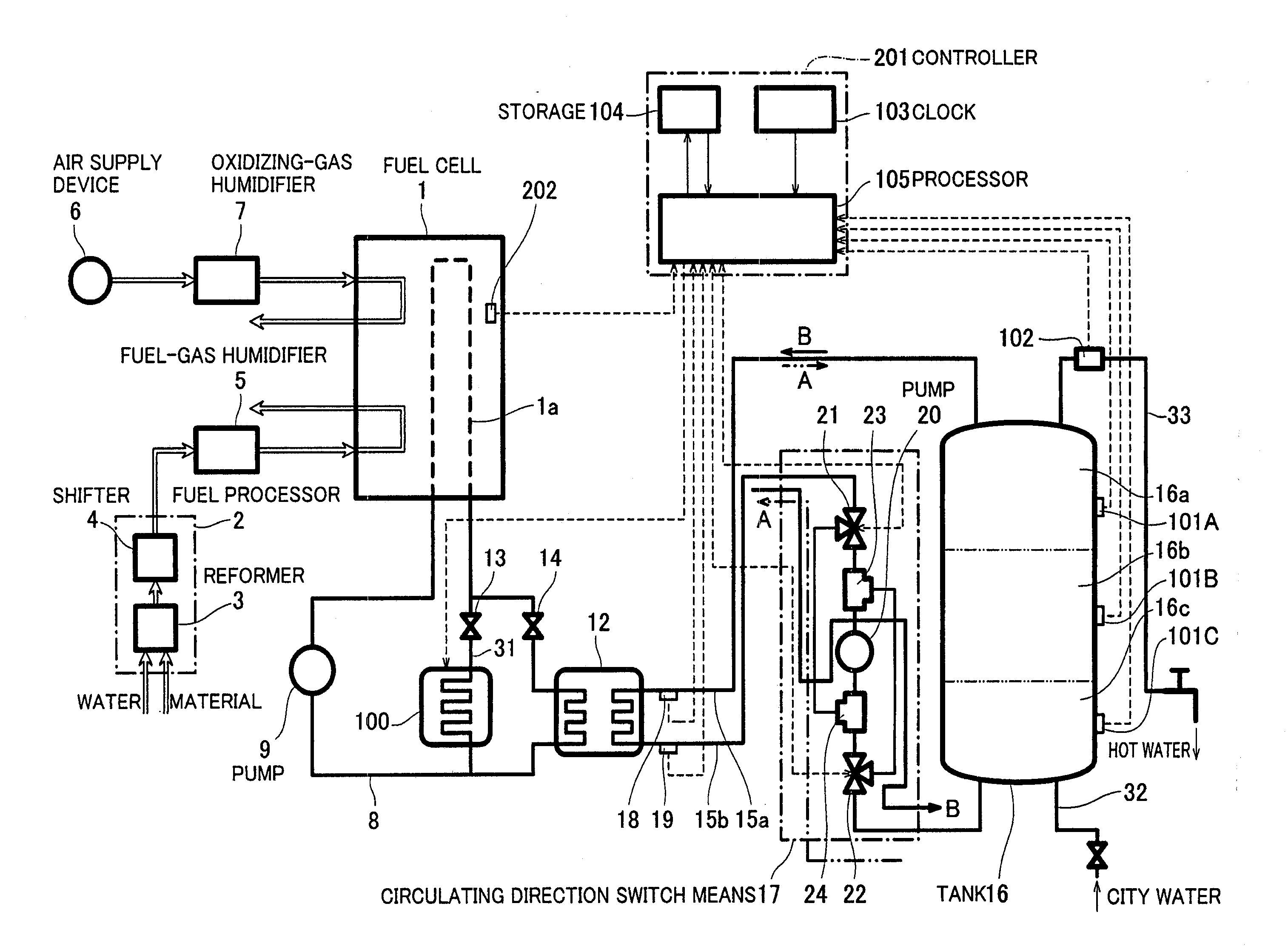
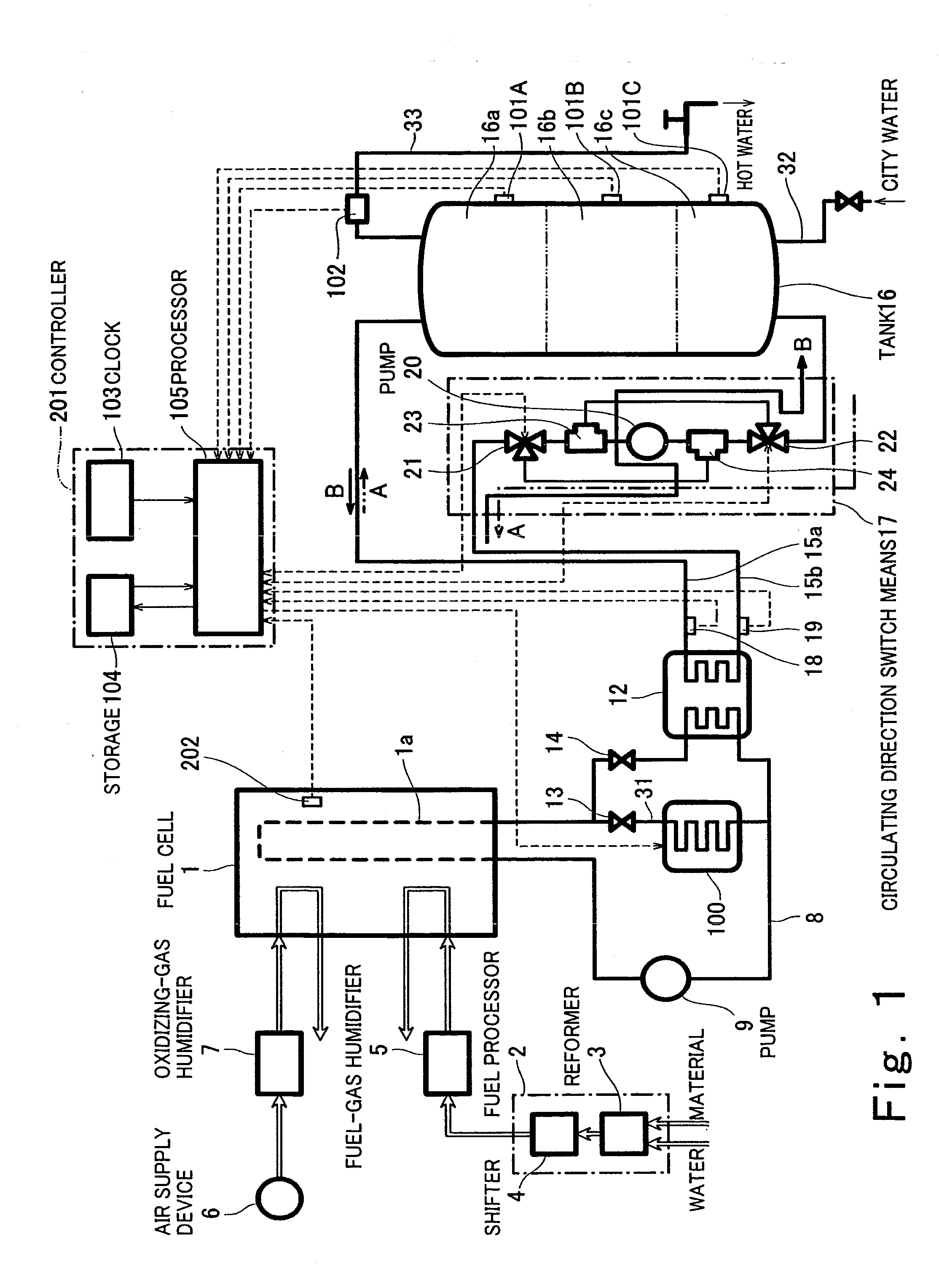
[0044]FIG. 1 is a block diagram showing a construction of a fuel cell cogeneration system according to a first embodiment of the present invention.

[0045]Turning to FIG. 1, the fuel cell cogeneration system (hereinafter simply referred to as cogeneration system) is chiefly divided into a construction of hardware and a configuration of a control system.

[0046]First of all, the construction of the hardware will be described. The cogeneration system comprises a fuel cell 1 configured to generate an electric power using a fuel gas and an oxidizing gas, a fuel processor 2 configured to generate a fuel gas from a material and water and to supply the fuel gas to the fuel cell 1, a fuel-gas humidifier 5 configured to humidify the fuel gas being supplied to the fuel cell 1 at a position in a flow path extending to the fuel cell 1, an air supply device 6 configured to supply air as an oxidizing gas to the fuel cell 1, and an oxidizing-gas humidifier 7 configured to humidify the air being suppli...

example 1 of embodiment 1

Alternative Example 1 of Embodiment 1

[0078]An alternative example 1 of the first embodiment will now be described.

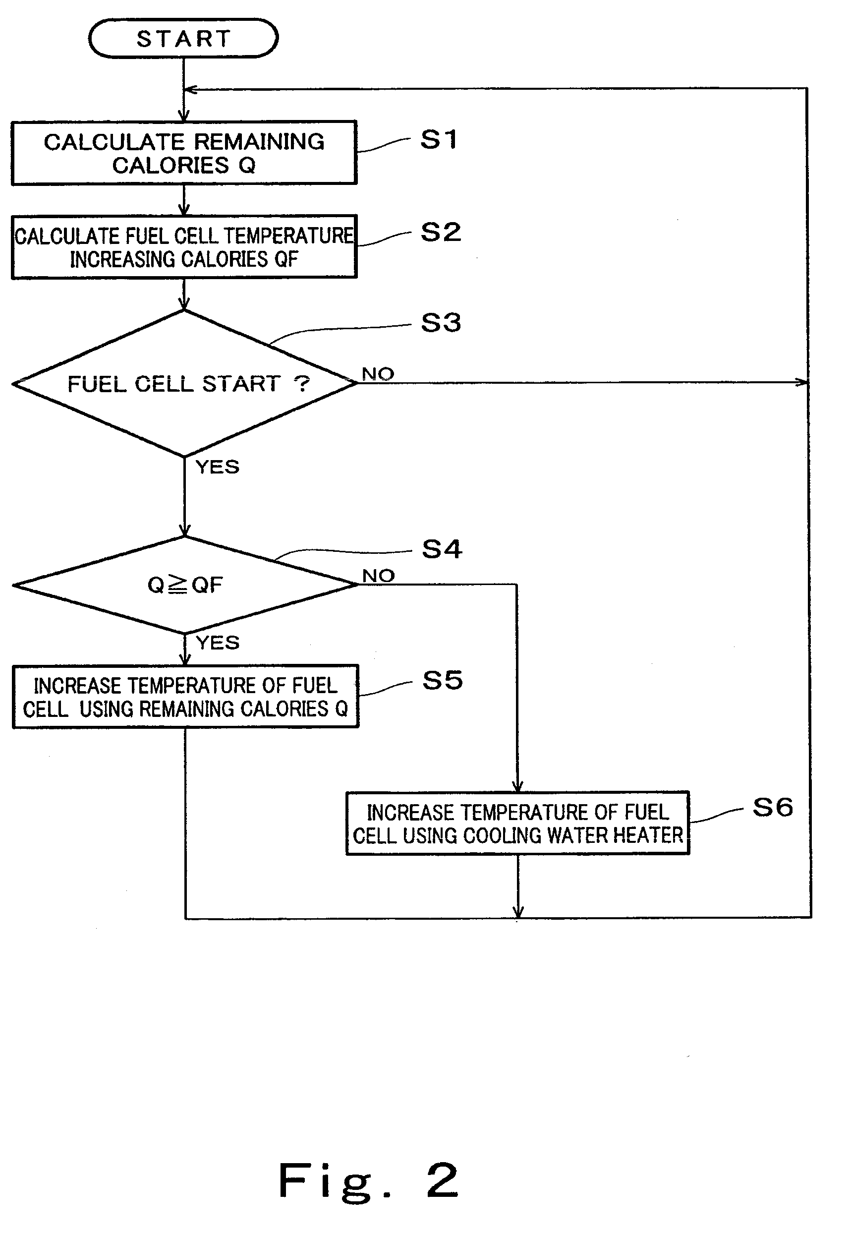
[0079]FIG. 3 is a flowchart showing an operation to select a temperature increasing means in a fuel cell cogeneration system according to the alternative example 1.

[0080]The construction of the alternative example 1 is substantially identical to that of the first embodiment in FIGS. 1 and 2 except for the operation to select the temperature increasing means under control of the controller 201. Specifically, as shown in FIGS. 1 and 3, the processor 105 of the controller 201 calculates the fuel cell temperature increasing calories QF in Step S2, and thereafter obtains stored hot water temperature TW and fuel cell operating temperature TO in Step S11. More specifically, the processor 105 converts the signal indicating the temperature of the upper portion 16a of the tank 16 which is input from the first tank temperature sensor 101A into a temperature according to a predeterm...

example 2 of embodiment 1

Alternative Example 2 of Embodiment 1

[0083]An alternative example 2 of the first embodiment will now be described. FIG. 4 is a flowchart showing an operation to select a temperature increasing means of a fuel cell cogeneration system according to the alternative example 2 of the first embodiment. FIG. 5 is a graph showing a time lapse variation in remaining calories for a day. FIG. 6 is a graph showing a time lapse variation in calories consumed by consumers for a day.

[0084]The construction of the alternative example 2 is substantially identical to that of the first embodiment in FIGS. 1 and 2 except for the operation to select the temperature increasing means under control of the controller 201. Specifically, as shown in FIGS. 1 and 4, the processor 105 of the controller 201 calculates the remaining calories Q according to the above described method in Step S1, and stores the calculated remaining calories Q and time input from the clock 103 as associated with each other in the stor...


PUM

PropertyMeasurementUnit
electric poweraaaaaaaaaa
temperatureaaaaaaaaaa
operating temperatureaaaaaaaaaa

Abstract

A method of operating a fuel cell cogeneration system comprises the steps of cooling a fuel cell by circulating an internal heat transfer medium through the fuel cell while the fuel cell is generating electric power, storing an external heat transfer medium in a heat utilization portion, detecting remaining calories of the heat utilization portion by a first detector provided at the heat utilization portion, increasing a temperature of the fuel cell to an operating temperature by carrying out a first temperature increasing operation, and increasing the temperature of the fuel cell to the operating temperature by carrying out a second temperature increasing operation.

Description

CROSS-REFERENCE TO RELATED APPLICATIONS[0001]The present application is a Continuation of U.S. patent application Ser. No. 10 / 894,261, filed Jul. 19, 2004 and entitled “Fuel Cell Cogeneration System,” the entire disclosure of which is here incorporated by reference.BACKGROUND OF THE INVENTION[0002]1. Field of the Invention[0003]The present invention relates to a fuel cell cogeneration system.[0004]2. Description of the Related Art[0005]FIG. 16 is a block diagram showing a construction of the conventional fuel cell cogeneration system (see Japanese Laid-Open Patent Application Publication No. 2002-042841, page 3 to 6, FIG. 1).[0006]Turning to FIG. 16, the fuel cell cogeneration system comprises a fuel cell 1 configured to generate an electric power using a fuel gas and an oxidizing gas, a fuel processor 2 configured to generate the fuel gas by subjecting a material to a steam reforming reaction and a shift reaction, a fuel-gas humidifier 5 configured to humidify the fuel gas to be su...

Claims


Application Information

Patent Timeline
Patent Type & Authority Applications(United States)
IPC IPC(8): H01M8/04H01M8/00H01M8/02
CPCF24D17/001F24D2240/26F24D2200/19H01M8/04029H01M8/04037H01M8/04052H01M8/04059H01M8/04358H01M8/04373H01M8/04425H01M8/04723H01M8/04738H01M8/04955H01M2250/405Y02E60/50Y02B90/16F24D2220/042F24D19/1051Y02P80/15Y02B30/18Y02B90/10
Inventor MIYAUCHI, SHINJIUEDA, TETSUYAYAMAMOTO, YOSHIAKI
Owner PANASONIC CORP
Why Eureka
Try Eureka