3D Biplane Microscopy

a microscope and biplane technology, applied in the field of three-dimensional (“ 3d”) sub100 nanometer resolution by biplane microscope imaging, can solve the problems of limited application of these techniques to two-dimensional (“2d”) imaging, limited spatial resolution, and concealing sub-structur

Active Publication Date: 2009-10-01
UNIVERSITY OF MAINE +1
View PDF62 Cites 74 Cited by
  • Summary
  • Abstract
  • Description
  • Claims
  • Application Information

AI Technical Summary

Benefits of technology

[0017]According to yet another embodiment, a method for tracking microscopic particles in 3D includes mounting a sample on a sample stage, the sample including luminescent particles. A small area of the sample is illuminated to cause luminescence light from primarily one particle of the luminescent particles. The light beam is selectively moved to illuminate different areas of the sample to track movement of the one particle, the different areas including the small area of the sample and corresponding to respective positions

Problems solved by technology

However, the slow progress in 3D super-resolution imaging has limited the application of these techniques to two-dimensional (“2D”) imaging.
Moreover, current understanding of fundamental biological processes on the nanoscale (e.g., neural network formation, chromatin organization) is limited because these processes cannot be visualized at the necessary sub-millisecond time resolution.
The diameter of most organelles is below the diffraction limit of light, limiting spatial resolution and concealing sub-structure.
But conventional particle-tracking fluorescence microscopy cannot temporally

Method used


Image

  • 3D Biplane Microscopy
  • 3D Biplane Microscopy
  • 3D Biplane Microscopy

Examples


Embodiment Construction

[0034]While this invention is susceptible of embodiment in many different forms, there is shown in the drawings and will herein be described in detail preferred embodiments of the invention with the understanding that the present disclosure is to be considered as an exemplification of the principles of the invention and is not intended to limit the broad aspect of the invention to the embodiments illustrated.

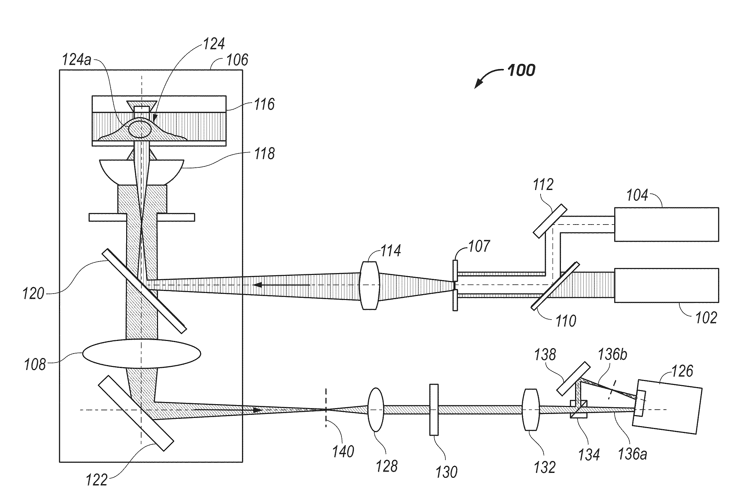
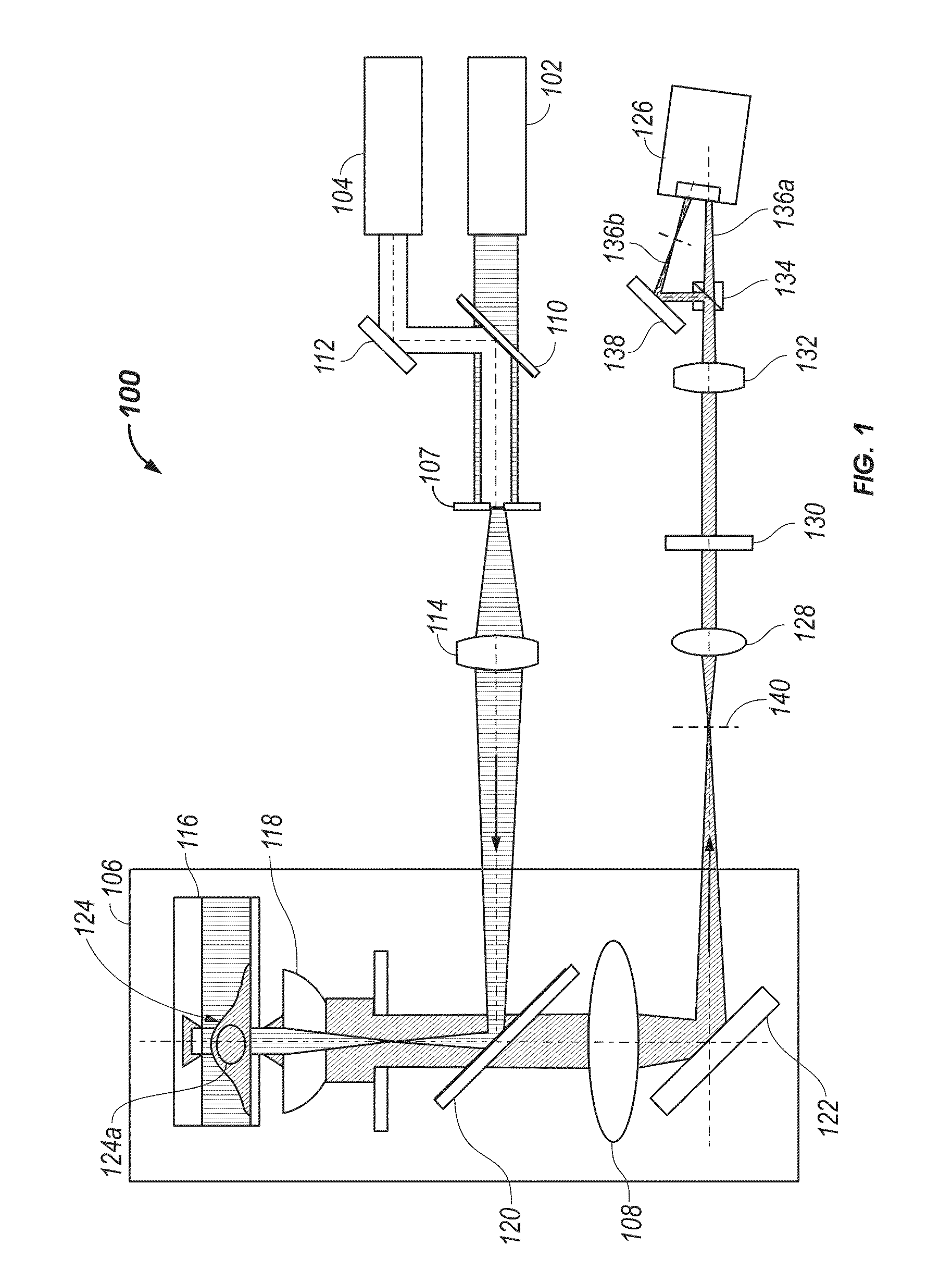
[0035]Referring to FIG. 1, a biplane (“BP”) microscope system 100 allows 3D imaging at an unmatched resolution well below 100 nanometers in all three dimensions, resulting in at least a 100-fold smaller resolvable volume than obtainable by conventional 3D microscopy. The BP microscope system 100 is optionally a BP FPALM system, which is generally based on a conventional FPALM design. However, in contrast to conventional FPALM design, the BP microscope system 100 includes a modified detection path that allows the simultaneous detection from two focal planes. The simultaneous dete...


PUM


Abstract

A microscopy system is configured for creating 3D images from individually localized probe molecules. The microscopy system includes a sample stage, an activation light source, a readout light source, a beam splitting device, at least one camera, and a controller. The activation light source activates probes of at least one probe subset of photo-sensitive luminescent probes, and the readout light source causes luminescence light from the activated probes. The beam splitting device splits the luminescence light into at least two paths to create at least two detection planes that correspond to the same or different number of object planes of the sample. The camera detects simultaneously the at least two detection planes, the number of object planes being represented in the camera by the same number of recorded regions of interest. The controller is programmable to combine a signal from the regions of interest into a 3D data.

Description

FIELD OF THE INVENTION[0001]The present invention relates generally to microscopic imaging and, more specifically, to three-dimensional (“3D”) sub-100 nanometer resolution by biplane microscope imaging.BACKGROUND OF THE INVENTION[0002]Until about a decade ago, resolution in far-field light microscopy was thought to be limited to ˜200-250 nanometers in the focal plane, concealing details of sub-cellular structures and constraining its biological applications. Breaking this diffraction barrier by the seminal concept of stimulated emission depletion (“STED”) microscopy has made it possible to image biological systems at the nanoscale with light. Additional details are provided in an article titled “Far-Field Optical Nanoscopy by Stefan W. Hell (316 Science, 1153-1158, May 25, 2007), which is incorporated herein by reference in its entirety. STED microscopy and other members of reversible saturable optical fluorescence transitions (“RESOLFT”) family achieve a resolution >10-fold beyo...

Claims


Application Information

Patent Timeline
IPC IPC(8): G01J1/58G01J3/30H04N13/00
CPCG02B21/16G02B21/367H04N13/0217G02B27/58H04N2013/0085G02B21/361H04N13/0253H04N13/218H04N13/254
Inventor BEWERSDORF, JOERGJUETTE, MANUEL F.GOULD, TRAVISHESS, SAM T.
Owner UNIVERSITY OF MAINE
Why Eureka
Try Eureka