Motor drive system

a technology of motor drive and drive shaft, which is applied in the direction of motor/generator/converter stopper, electric generator control, pulse manipulation, etc., can solve the problems of surplus power consumption, surplus power consumption in either regeneration and power running, and surplus power consumption in consumption operation. to achieve the effect of preventing the generation of overvoltage and consummating surplus power

Active Publication Date: 2009-10-01
DENSO CORP
View PDF6 Cites 55 Cited by
  • Summary
  • Abstract
  • Description
  • Claims
  • Application Information

AI Technical Summary

Benefits of technology

[0007]The invention has been made for overcoming the above problems, and an object of the invention is to provide a motor drive system having a control structure that can consume a surplus power while performing torque-following control, without causing instability in motor control.

Problems solved by technology

According to the above motor drive system, the consuming operation can consume the surplus power in the AC motor.
Therefore, even when a torque requested to the AC motor changes, the output torque can follow the torque command value, and a surplus power can be consumed when necessary (e.g., when the AC motor instantaneously generates a large amount of power).
Further, the surplus power can be consumed in either of the regeneration and the power running, i.e., independently of the operation state of the AC motor.

Method used


Image

  • Motor drive system
  • Motor drive system
  • Motor drive system

Examples


first embodiment

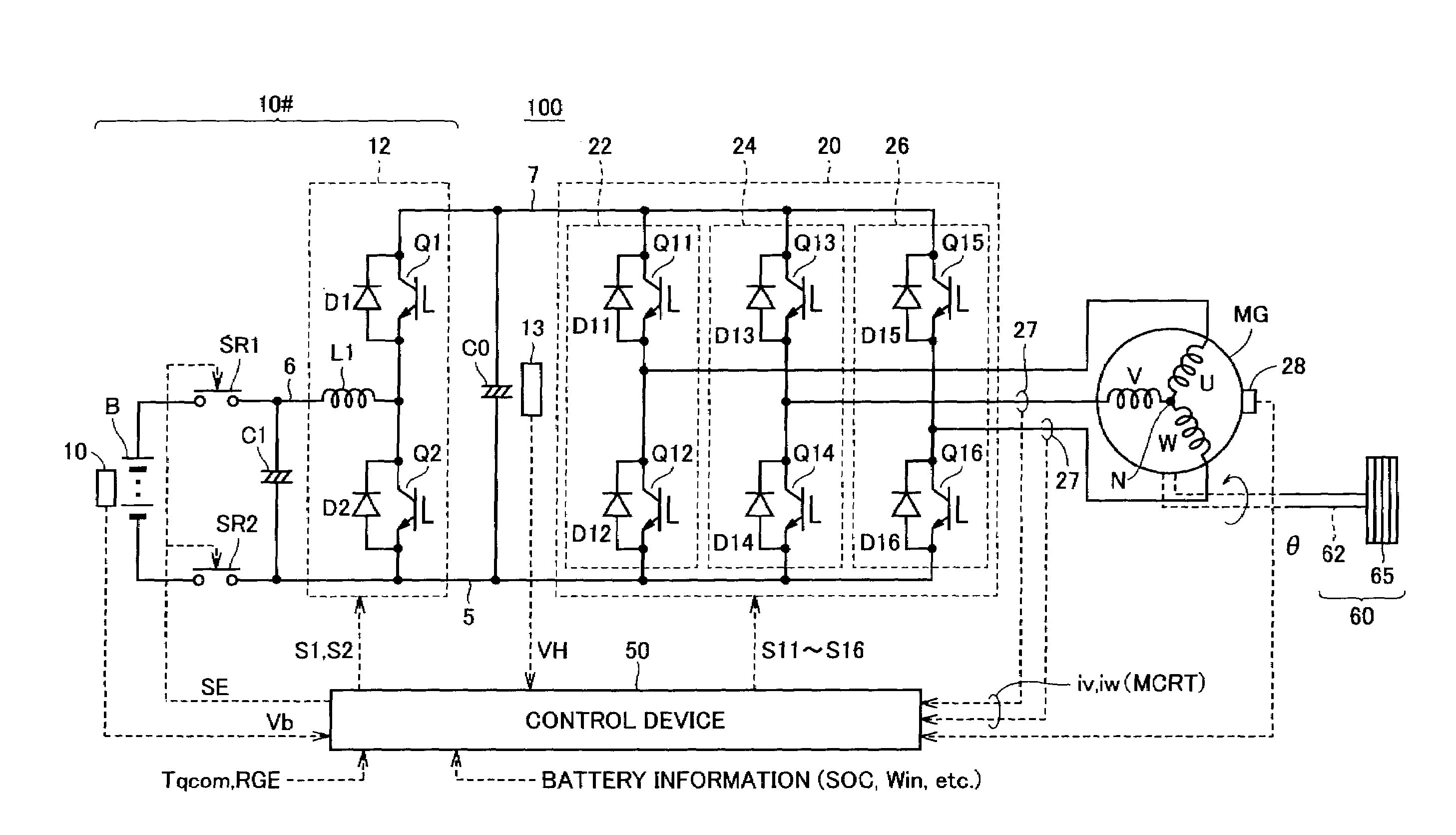
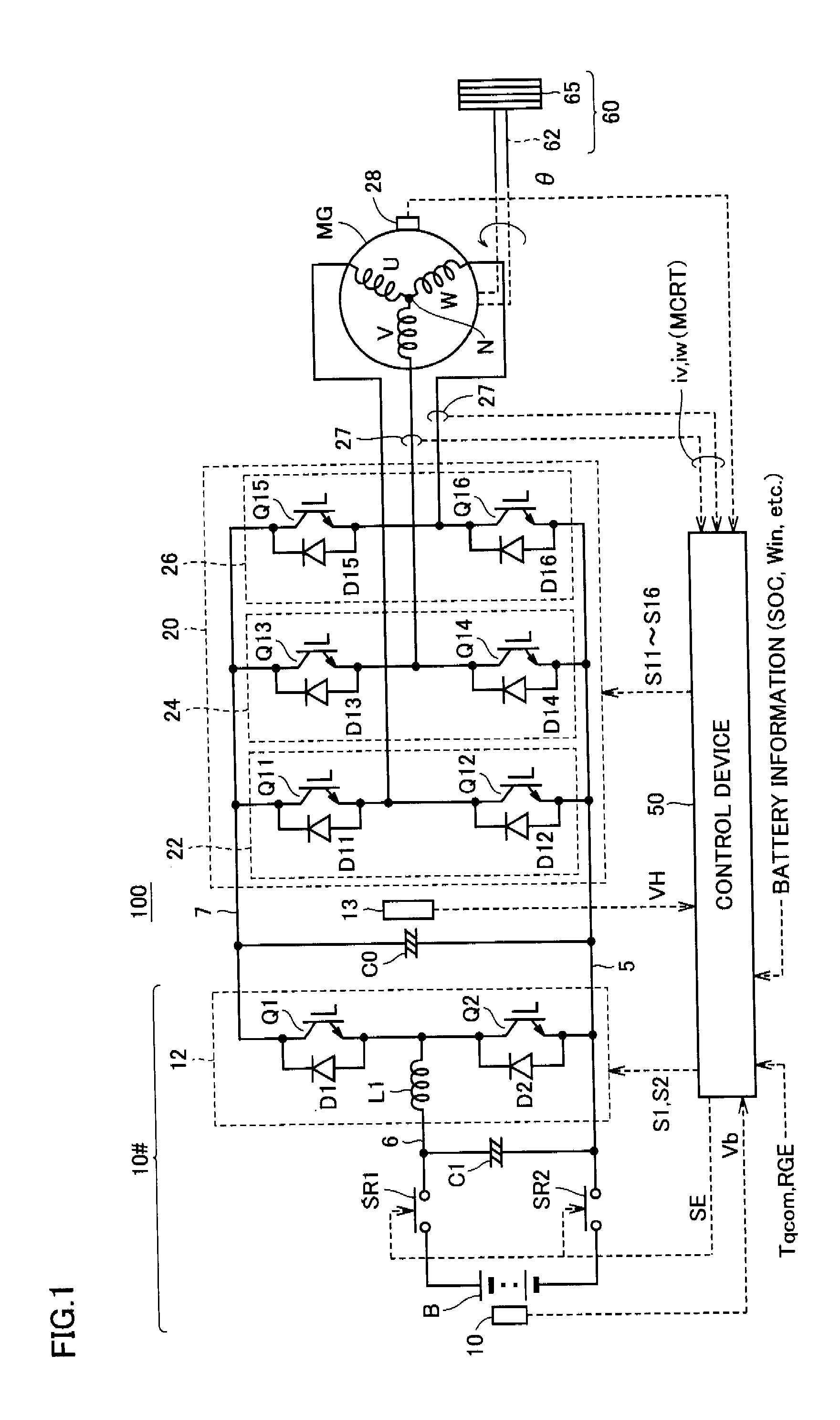
[0067]FIG. 1 shows a whole structure of a motor drive system according to an embodiment of the invention.

[0068]Referring to FIG. 1, a motor drive system 100 according to an embodiment of the invention includes a DC voltage generating unit 10#, a smoothing capacitor C0, an inverter 20, a control device 50 and an AC motor MG.

[0069]A load 60 is driven to rotate by an output torque of AC motor MG. For example, load 60 includes a drive shaft 62 coupled for transmitting an output torque of AC motor MG, and a drive wheel 65 that is driven to rotate according to a rotation of drive shaft 62.

[0070]As described above, AC motor MG is used typically as a driving electric motor for driving the drive wheels of a hybrid car or an electric car. Alternatively, AC motor MG may be configured to have a function of an electric generator that is driven by an engine, and may be configured to have both the functions of the electric motor and the generator such that regenerative power generation is performe...

first setting example

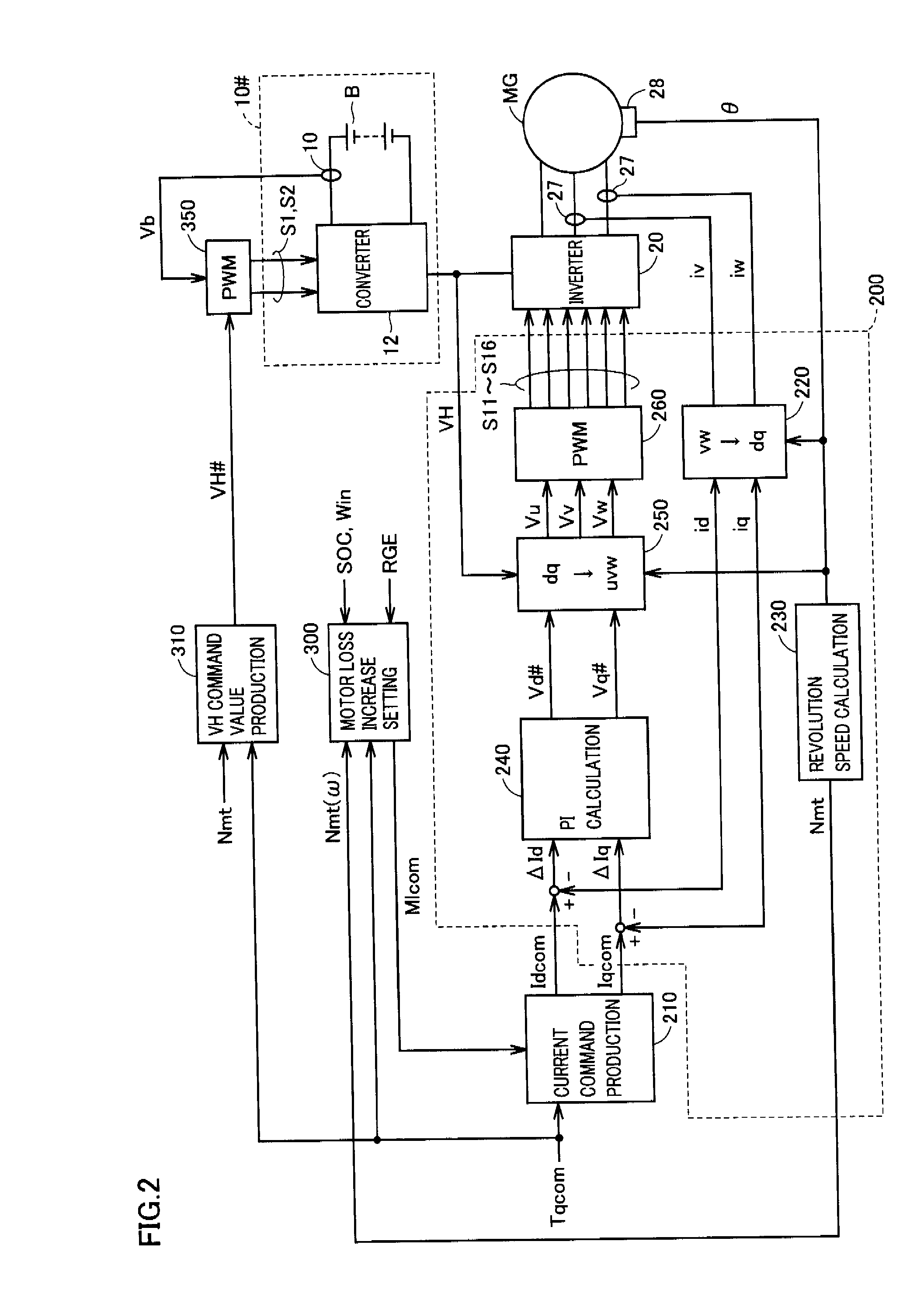
[0129]Referring to FIG. 7, motor loss increase setting unit 300 receives information for determining the intentional power loss quantity in AC motor MG, and more specifically receives control signal RGE, torque command value Tqcom and motor revolution speed Nmt (angular rotation speed ω) indicating the operation state of AC motor MG.

[0130]Motor loss increase setting unit 300 sets motor loss increase setting value Mlcom based on estimation of the generated power of AC motor MG, e.g., according to a flowchart in FIG. 8.

[0131]Referring to FIG. 8, in step S200, motor loss increase setting unit 300 estimates a generated power Pgn in AC motor MG from torque command value Tqcom and angular rotation speed ω during the regenerative operation of AC motor MG. For example, generated power Pgn can be estimated from the following equation (1):

Pgn=Tqcom·ω  (1)

[0132]Further, in step S210, motor loss increase setting unit 300 compares generated power Pgn and regeneratable power Pin in AC motor MG. R...

second setting example

[0136]Referring to FIG. 7 again, motor loss increase setting unit 300 further receives a detected value of system voltage VH obtained by voltage sensor 13.

[0137]Motor loss increase setting unit 300 may set motor loss increase setting value Mlcom based on monitoring of system voltage VH according to a flowchart of FIG. 9.

[0138]Referring to FIG. 9, motor loss increase setting unit 300 obtains the detected value of system voltage VH (DC link voltage of the inverter) from voltage sensor 13 in step S250, and compares system voltage VH with a determination voltage Vjd to determine whether the voltage inside the system has risen or not. Determination voltage Vjd is set to a value that is lower than an overvoltage damaging a device in the motor drive system and is higher than the command value of system voltage VH.

[0139]When the system voltage rises (YES in step S260), motor loss increase setting unit 300 sets motor loss increase setting value Mlcom larger than zero (Mlcom>0) in step S270 s...


PUM


Abstract

In a drive system of an AC motor in which a motor current is feedback-controlled, a motor current command is produced in a normal operation according to a torque command value on an optimum efficiency characteristic line so as to select an optimum current phase maximizing an output torque with a constant motor current amplitude. Conversely, when the AC motor produces an excessively generated power exceeding a regeneratable power quantity of the AC motor, a consuming operation is performed for intentionally increasing the power loss in the AC motor. In the consuming operation, the motor current command is produced according to the torque command value on a loss increase characteristic line to change the current phase from the above optimum value. Thereby, the power loss in the AC motor can be increased to consume the surplus power without causing instability in the motor control.

Description

TECHNICAL FIELD[0001]The present invention relates to a motor drive system, and particularly to a motor drive system controlling drive of an AC motor by feedback control of a motor current.BACKGROUND ART[0002]A structure including a rechargeable DC power supply, an inverter and an AC motor has been known as a typical motor drive system. This motor drive system is configured as follows. During power running of the AC motor, a power supplied from the DC power supply drives and controls the AC motor so that the power can be bidirectionally supplied and received between the DC power supply, the inverter and the AC motor. Also, during a regenerative operation of the AC motor, the inverter converts the regenerative power supplied from the AC motor into a DC voltage, which can be used for charging the DC power supply by it.[0003]In this motor drive system, the AC motor may generate a power exceeding an acceptable power of the input side (DC power supply side) and thereby may generate a sur...

Claims


Application Information

Patent Timeline
Patent Type & Authority Applications(United States)
IPC IPC(8): H02P3/14B60L50/16H02P3/18H02P21/00H02P21/22H02P21/36H02P23/07H02P27/04H02P27/08
CPCB60L7/16Y02T10/648B60L11/12B60L15/02B60L15/025B60L2210/20H02P3/18H02P21/06H02P21/148H02P29/024H02P2201/09H02P2205/05Y02T10/643Y02T10/646Y02T10/7077Y02T10/725B60L11/08B60L50/13B60L50/15H02P21/00H02P21/20H02P29/0241Y02T10/64Y02T10/7072Y02T10/72H02P3/14H02P27/04
Inventor SUHAMA, MASAYOSHIOKAMURA, MASAKISATO, EIJI
Owner DENSO CORP
Why Eureka
Try Eureka